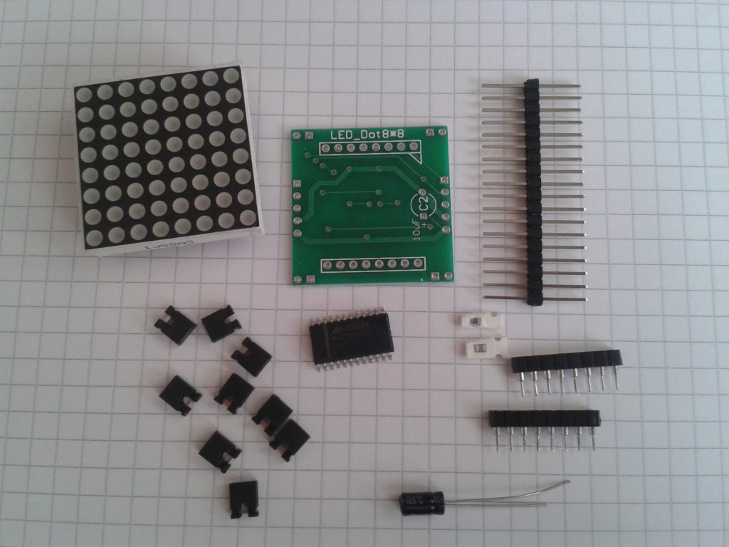
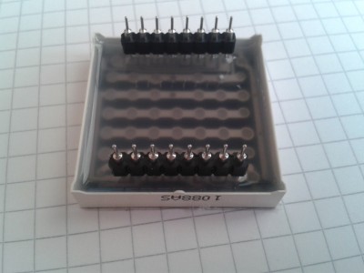
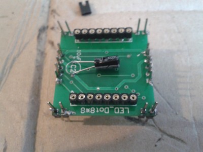
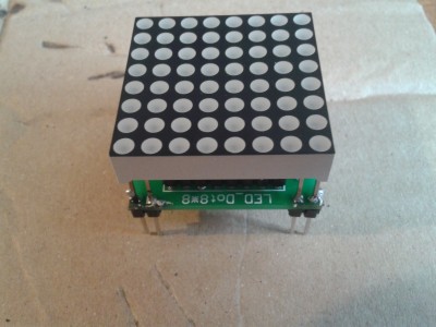
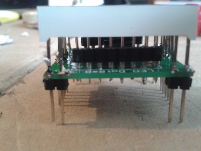
The assembly and a square LED matrix are shown since those modules are not supplied soldered together. A library for the MAX7219 IC for subsequent projects is also installed, which makes control with a Python script very easy.
Overview
The following components are available:
The following hardware parts are needed:
- square matrices (9 or more are ideal)
- soldering iron
- solder
- soldering grease (optimal)
- fireproof underlay (a thick box does it too)
Assembly
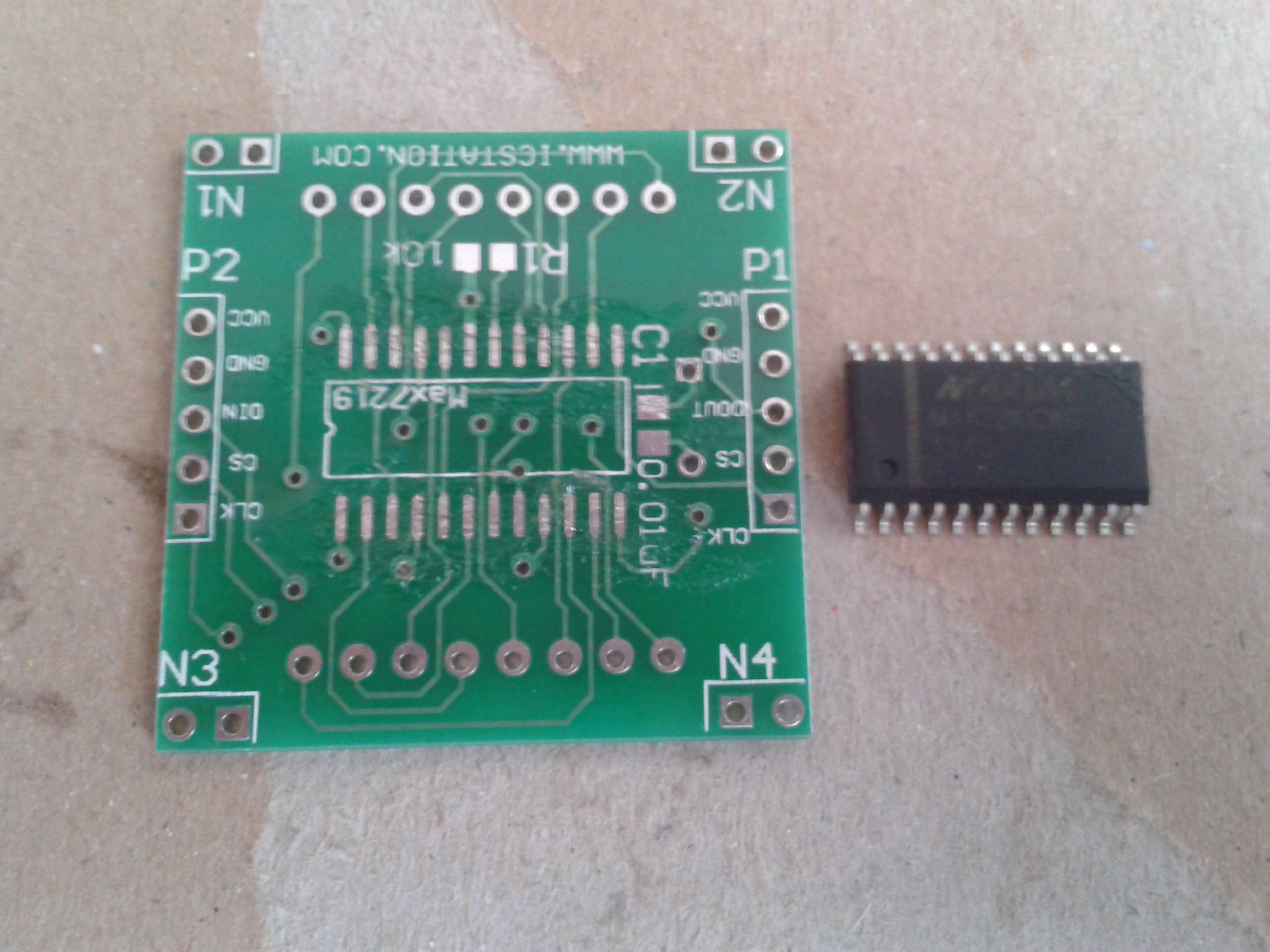
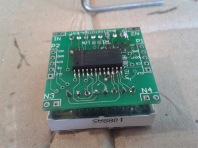
First, the IC MAX7219 has to be soldered to the board. Alignment is important here. Make sure that the labels “N3” and “N4” are at the bottom, as well as the dot on the module at the bottom left:
First coat the contact surfaces with solder grease and position the module on the plate. It is best to solder two ends first so that it does not slip. Then you can carefully solder each pin to the contact area. Since the distance is very small, you should make sure that no two pins are accidentally connected to each other, as this can cause a short circuit later. Take your time with that.
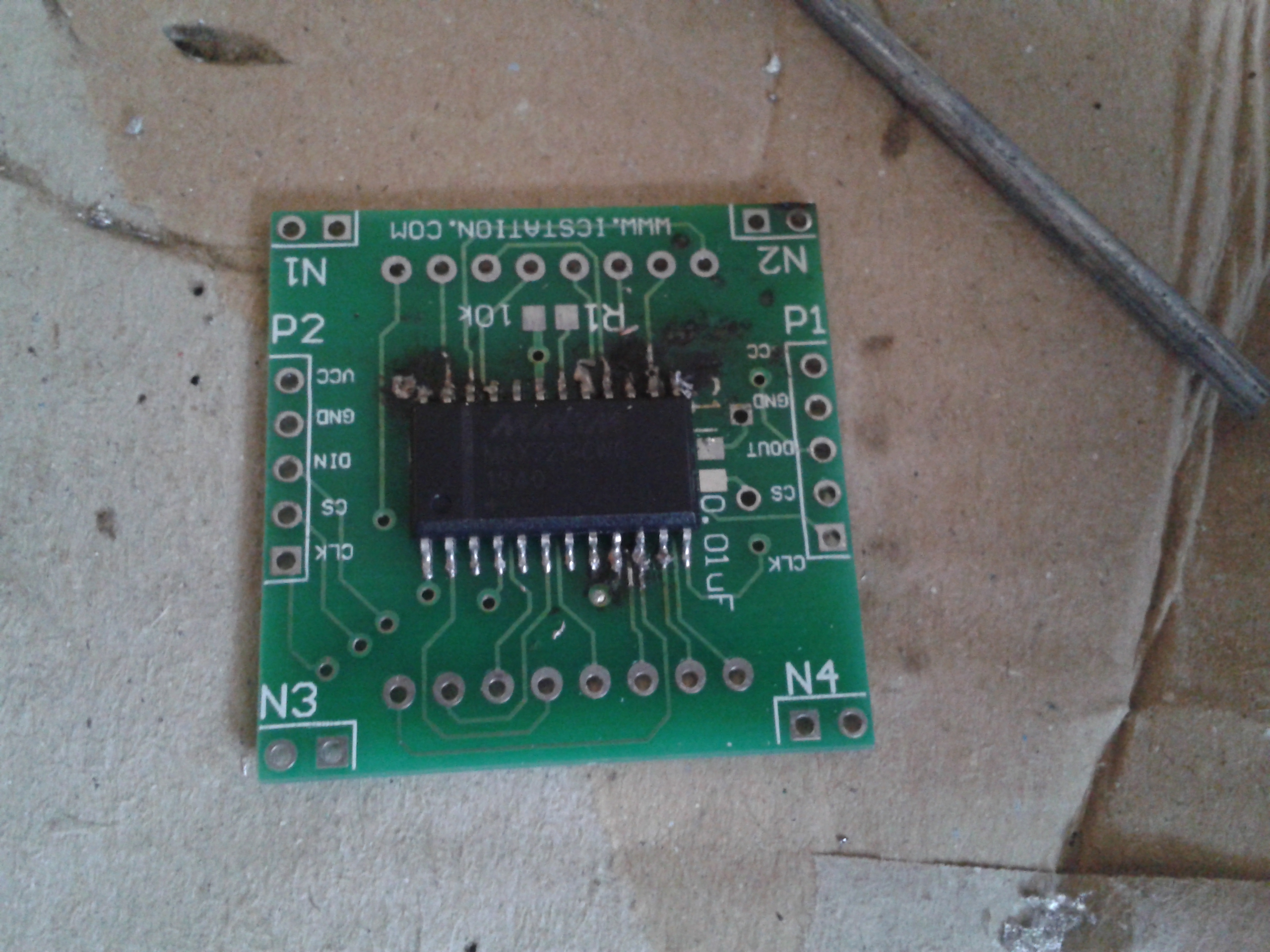
If all contacts are soldered, it should look something like this:
Next up are the two-pin headers for the actual dot matrix. So that everything fits later, you should put it on now.
Now you can put them on the board and solder them firmly. Attention: The side with the component must face you and not be covered by the LEDs. Here soldering is easier again, as there is more space between the pins.
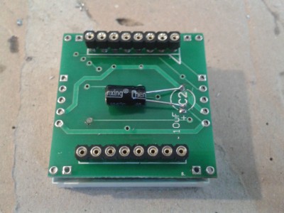
Next up is the cuboid capacitor. To do this, remove the LED plate again and solder the capacitor. The longer side of the wire comes into the hole next to which + is printed and the shorter ones in the other hole so that it looks like this (I shortened the wire a little more and bent the capacitor after soldering to save space):
The following step is a bit difficult in my opinion since the components are very small. There were two approximately 1 mm large components that are difficult to hold in position.
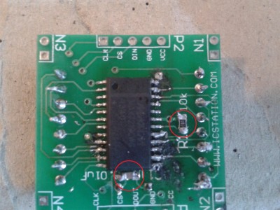
First, take the resistor: it is a bit larger and it says 103 (or 1002), which stands for 10k ohms. This comes between the contact areas at R1.
The other component comes between the contact surfaces at C1 (0.01uF). The alignment of both doesn’t matter.
In the following picture I have circled the two places:
With that, the majority is done. Only the connecting pins are still missing. Make 2 of them 2 to each other and solder them to the bottom (the side on which the cuboid capacitor is). You divide the remaining pins into 4 parts, 2 pins next to each other and solder them to the corners:
That’s it. You can now put the LED module back on and connect it.
The connections are as follows:
Installation
I use this library to control the matrix:
git clone https://github.com/rm-hull/max7219.git&& cd max7219After the installation
sudo python setup.py installThe test file can be started and the LED matrix should light up.
sudo python examples/test.pyIf it flashes now everything worked, otherwise try to plug the LED module the other way around on the board.

