")
After we have defined the basic functions for our Raspberry Pi robot in the first part, we now want to use them by letting it follow a drawn line. To do this, we attach two optical infrared sensors (Line Follower: TCRT5000) to the body of the robot. If the line is lost, it is automatically searched for at an angle of 45° (adjustable) on both sides. If nothing is found, the robot stops.
This tutorial assumes that the functions of the first robot tutorial have already been implemented. If not, you should follow the previous tutorial first before proceeding here.
Required Hardware Parts

As additional accessories, only two line follower modules are required in this tutorial (and of course female-female jumper cables). I also used hot glue to attach them. Black insulating tape is particularly suitable as a line.
It is also possible to use more than two IR Line Follower sensors, but the code must then also be edited accordingly. If you are recreating the project the way I did it, it is advisable to stick with two sensors.
Here you can already see a video of how the robot can later follow a line:
IR Line Follower Function
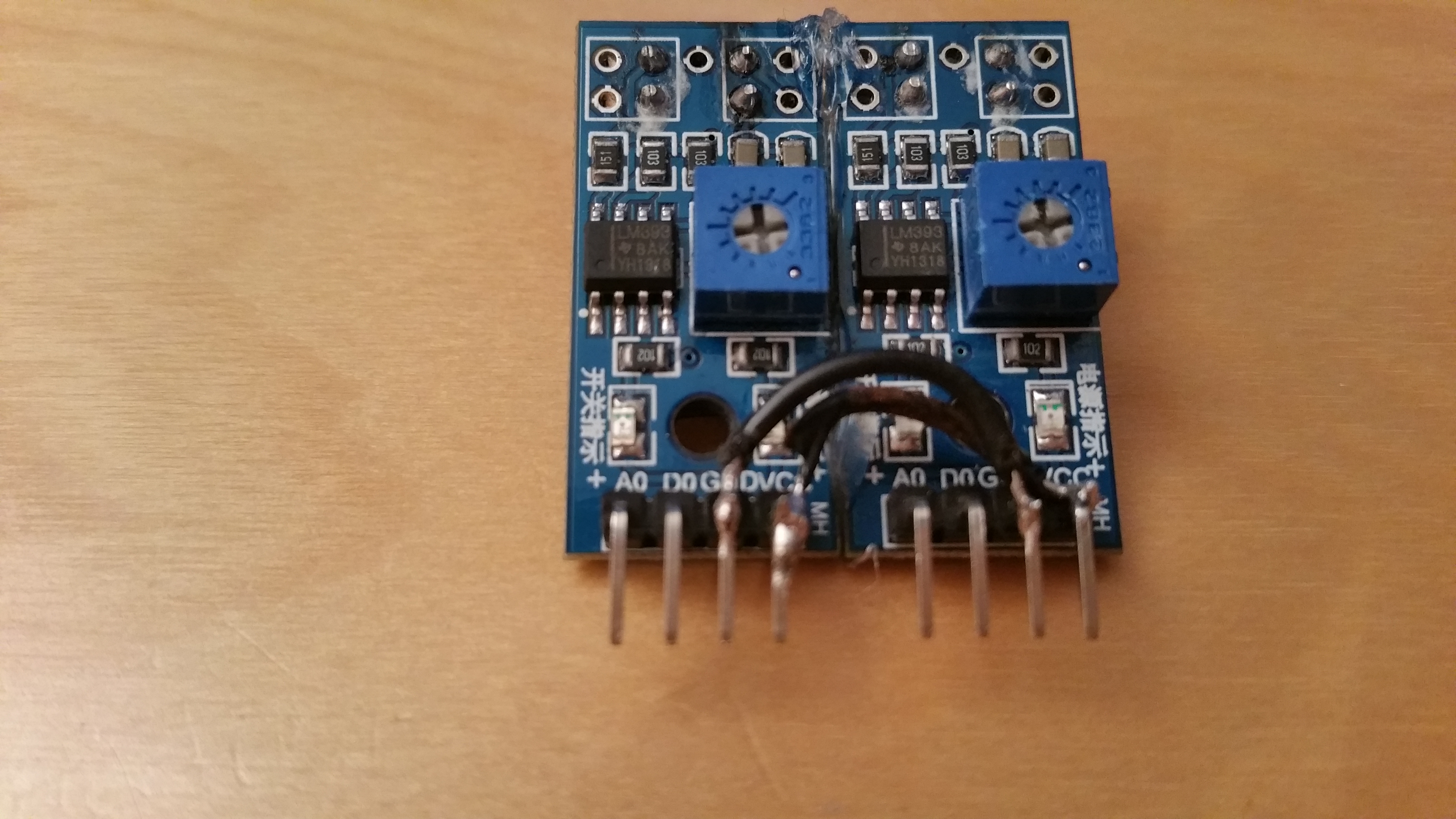
The TCRT500 (datasheet) as a module has 4 pins: VCC, GND and an analog and digital output. The analog output is unimportant in this case, as we can already see from the digital pin whether the sensor is above a line. In addition, there is also an LED which lights up if there is no line underneath (see the following images).
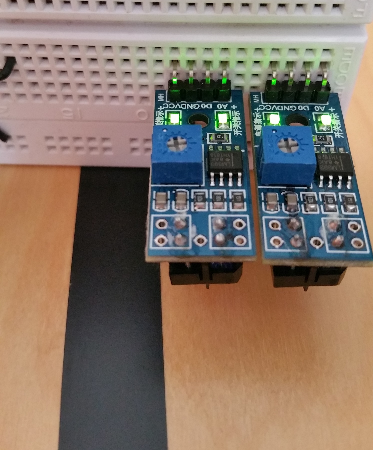
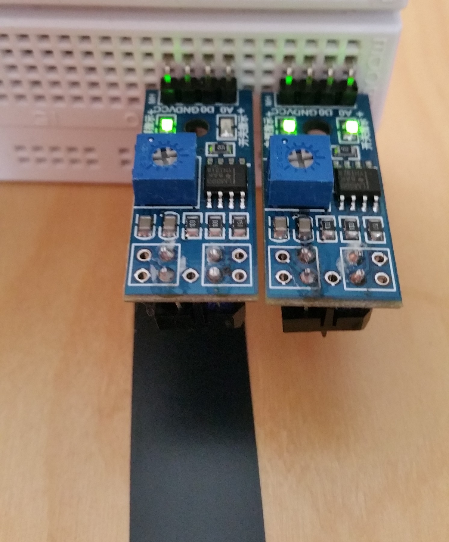
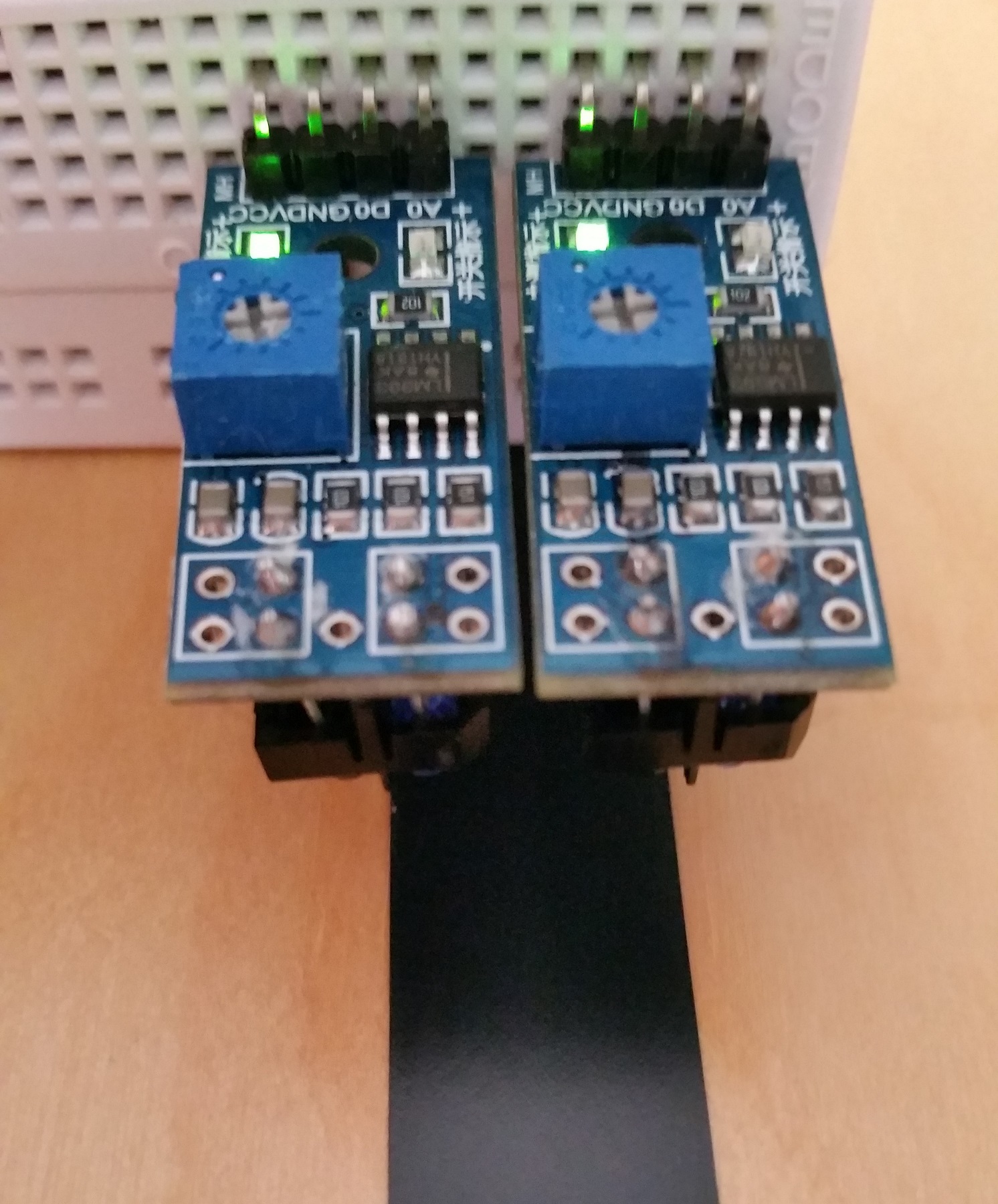
One of the two IR LEDs sends an invisible (infrared) signal. If this is now absorbed, the sensor is in all probability on a black line. Since the same effect is achieved as soon as the module is too far away from a surface, it should be ensured that the distance to the floor is approx. 1 to 1.5cm.
The choice of surface is also important: Smooth, slightly reflective surfaces are best (parquet, tiles, possibly also a floor covered with paper). The best contrast to this is the non-reflective black insulating tape, as I, therefore, used it.
Assembly and Connection
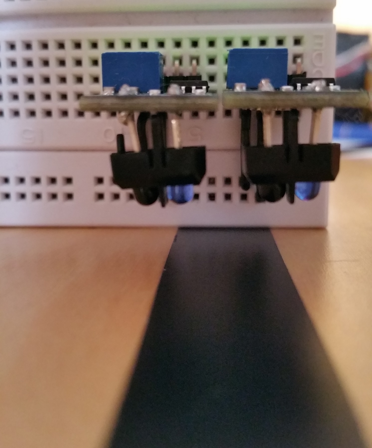
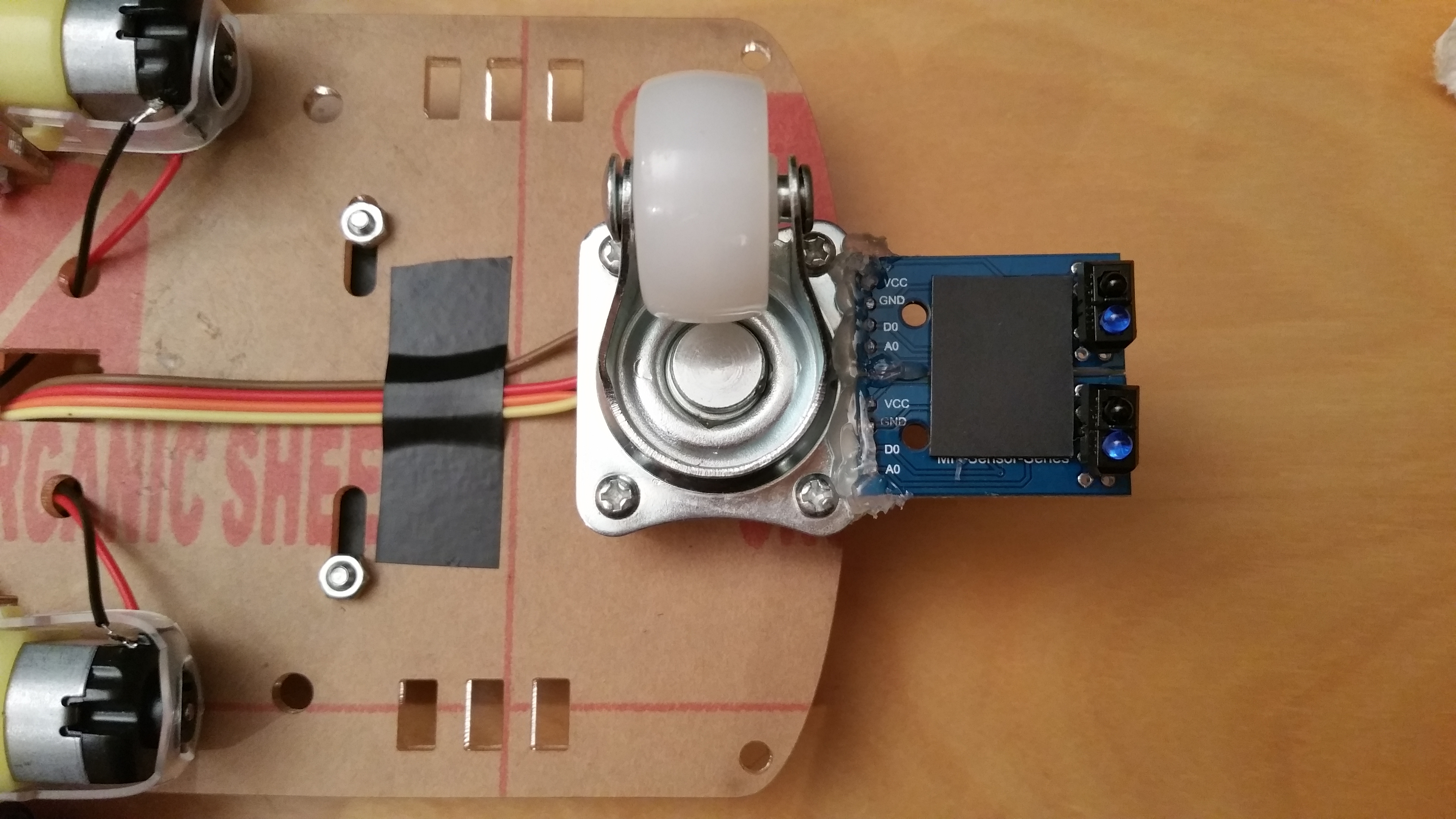
Before we attach the sensors, it is advisable to connect them: To do this, I attached both to each other on the sides with a little hot glue. After this has dried, I soldered the two VCC and GND pins to each other with a wire so that fewer cables are required. After attaching the jumper cables, I glued the assembled modules to the front wheel of the body with more hot glue. It is important that the distance to the ground is not too great. You should test the perfect height before attaching it (I fit exactly one finger underneath).
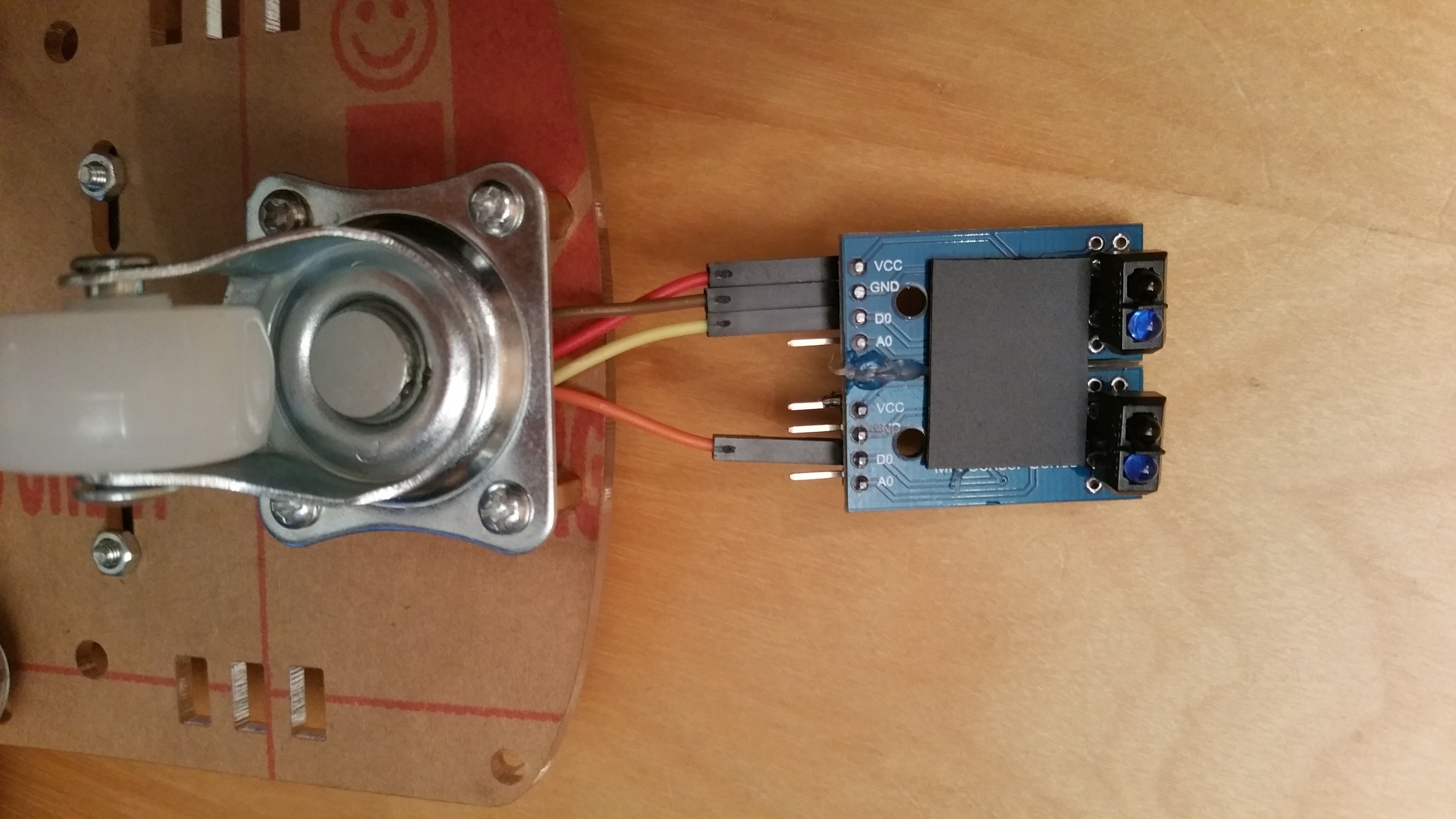
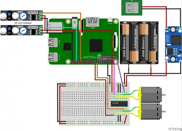
The further connection to the Raspberry Pi is very simple: VCC is connected as usual to the 3.3V pin of the Raspberry Pi, GND to GND and the digital output (D0) to a free GPIO pin. I chose GPIO 6 (right) and 19 (left) for this.
With the motors attached before and our motor driver IC, the schematic structure now looks like this:
Extended Code of the Raspberry Pi Robot
In order to follow the line, there are different modes that are checked: If both sensors detect the line, it is simply driven straight ahead, if only one of the two sensors detects the line, it is driven a little in the other direction. As soon as both sensors detect something again, the vehicle will drive straight ahead again. If neither of the two sensors detects something, an area (degrees_to_search) is searched for on both sides. If something is found, it continues as before. If not, the search ends and the robot stops.
So first we switch back to the previously created folder to create another file. This will later be responsible for all actions of the robot and control them.
sudo nano robot.py
The content is as follows:
|
1 2 3 4 5 6 7 8 9 10 11 12 13 14 15 16 17 18 19 20 21 22 23 24 25 26 27 28 29 30 31 32 33 34 35 36 37 38 39 40 41 42 43 44 45 46 47 48 49 50 51 52 53 54 55 56 57 58 59 60 61 62 63 64 65 66 67 68 69 70 |
import RPi.GPIO as GPIO import time from l293d import L293D class Robot(): def __init__(self, motor_left_pin1=17, motor_left_pin2=27, motor_right_pin1=23, motor_right_pin2=24, line_follow_pin_left=19, line_follow_pin_right=6 ): GPIO.setmode(GPIO.BCM) GPIO.setwarnings(False) # init modules self.motor = L293D(motor_left_pin1, motor_left_pin2, motor_right_pin1, motor_right_pin2) self.line_follow_pin_left = line_follow_pin_left self.line_follow_pin_right = line_follow_pin_right GPIO.setup(self.line_follow_pin_left, GPIO.IN) GPIO.setup(self.line_follow_pin_right, GPIO.IN) def lineFollowModeOn(self): status_left = False status_right = False while True: status_left = bool(GPIO.input(self.line_follow_pin_left)) # False: not on line / sensor too distant from bottom status_right = bool(GPIO.input(self.line_follow_pin_right)) # True: on line if status_left and status_right: # one the line, follow straight on self.motor.forward() elif status_left: # line is on the left, move left (motor right) self.motor.forwardRight() elif status_right: # line is on the right, move right (motor left) self.motor.forwardLeft() else: # have gone astray, search line. first go back some cm self.motor.backward() time.sleep(7.5/self.motor.DIST_PER_SEC) self.motor.stop() # rotate x degrees to search the line degrees_to_search = 45.0 self.motor.forwardRight() s = GPIO.wait_for_edge(self.line_follow_pin_left, GPIO.RISING, timeout=int(1000 * self.motor.SEC_PER_TURN / 360.0 * degrees_to_search)) self.motor.stop() if s is not None: # line found, continue continue else: # nothing found, go back to original position self.motor.backwardRight() time.sleep(self.motor.SEC_PER_TURN / 360.0 * degrees_to_search) # search in other side self.motor.forwardLeft() s = GPIO.wait_for_edge(self.line_follow_pin_right, GPIO.RISING, timeout=int(1000 * self.motor.SEC_PER_TURN / 360.0 * degrees_to_search)) self.motor.stop() if s is not None: # line found, continue print("fund") continue else: # line could not be found, go back to original position, stop self.motor.backwardLeft() time.sleep(self.motor.SEC_PER_TURN / 360.0 * degrees_to_search) self.motor.stop() break time.sleep(0.001) |
And a first test can already be carried out. Create a test track (preferably not too sharp curves) and execute the following Python code:
|
1 2 3 4 |
from robot import Robot rob = Robot(17, 27, 23, 24, 19, 6) rob.lineFollowModeOn() |
The robot should now follow the line properly. Possibly, you can still adapt the angle (degrees_to_search) to your wishes. The robot can now e.g. already be used as a Pokémon Go egg breeder 😀
In the next Raspberry Pi Robot Tutorial, we will control the robot via infrared remote control.