")
Anyone who has ever thought of a car PC has certainly dealt with radio reception. Now there are not too many possibilities to use the Pi as an FM receiver, but one is the Si4703 module, which is used here.
In a previous tutorial, I have already shown how to use the Raspberry Pi as a
radio transmitter. This part is about how to receive and play radio frequencies.
Required Hardware Parts
To use your Raspberry Pi as a radio receiver, you will need the following:
- Si470x Receiver Module
- Aux Cable / Headphones
- Female-Female Jumper Cable
Setup
The connection of the Si470x module is as follows:
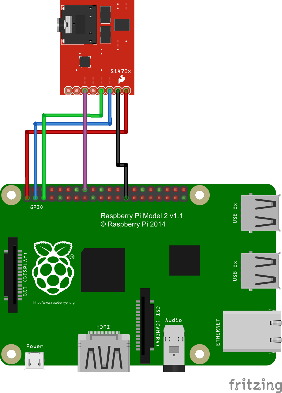
| Raspberry Pi | SI470x |
|---|---|
| 3.3V (Pin 1) | 3.3V |
| GND (Pin 6) | GND |
| SDA (Pin 3) | SDIO |
| SCL (Pin 5) | SCLK |
| GPIO23 (Pin 16) | RST |
On the schematic picture, I have connected GND to Raspberry Pi pin 25, which is also a ground connection.
Preparation
(In order to compile the software, wiringPi must be installed, if you have not already done so, you can read how to do it here)
First, we activate SPI and I2C. If you already did that in a previous tutorial, you can skip this step.
sudo raspi-config
Under “Interfacing Options” there is the entry “I2C”, which we should activate. For older Raspbian versions, the entries in the file /etc/modprobe.d/raspi-blacklist.conf must be commented out (with a #).
Then we edit the modules file:
sudo nano /etc/modules
At the end of the file we add the following two lines:
|
1 2 |
i2c-bcm2708 i2c-dev |
Lastly, we install the necessary tools if they are not already available.
sudo apt-get update
sudo apt-get install i2c-tools
Software
git clone https://github.com/achilikin/RdSpi && cd RdSpi
Then we compile:
make
Before we start, however, the module must first be activated via I2C. For this we create another script in this folder:
sudo nano i2c-init.c
|
1 2 3 4 5 6 7 8 9 10 11 12 13 14 15 16 17 18 19 20 21 22 23 24 25 26 |
/* i2c-init.c */ #include <wiringPi.h> int main() { int resetPin = 23; // GPIO23 int sdaPin = 0; // GPIO0 /* Setup GPIO access in BCM mode */ wiringPiSetupGpio(); /* Set pins as output */ pinMode(resetPin, OUTPUT); pinMode(sdaPin, OUTPUT); /* A low SDA indicates a 2-wire interface */ digitalWrite(sdaPin, LOW); /* Put chip into reset */ digitalWrite(resetPin, LOW); /* 1ms delay to allow pins to settle */ delay(1); /* Bring chip out of reset with SDIO set low and SEN pulled high (with pull-up resistor) */ digitalWrite(resetPin, HIGH); return 0; } |
After saving (CTRL + O, CTRL + X) we compile it.
gcc -o i2c-init i2c-init.c -lwiringPi
This script initializes the module so that it can be used (it must be re-initialized after each reboot, so it would make sense to set the program to Autostart).
sudo ./i2c-init
To test if it has been detected, you can type i2cdetect -y 1, which should produce such an output:
     0  1  2  3  4  5  6  7  8  9  a  b  c  d  e  f
00:          -- -- -- -- -- -- -- -- -- -- -- -- --
10: 10 -- -- -- -- -- -- -- -- -- -- -- -- -- -- --
20: -- -- -- -- -- -- -- -- -- -- -- -- -- -- -- --
30: -- -- -- -- -- -- -- -- -- -- -- -- -- -- -- --
40: -- -- -- -- -- -- -- -- -- -- -- -- -- -- -- --
50: -- -- -- -- -- -- -- -- -- -- -- -- -- -- -- --
60: -- -- -- -- -- -- -- -- -- -- -- -- -- -- -- --
70: -- -- -- -- -- -- -- --
Test the Raspberry Pi FM Receiver
Once the module has been initialized, we can use the aux cable to connect our speakers/headphones (which serve as antennas) and search for stations.
First we have to reset the receiver:
sudo ./rdspi resetYou can set a frequency and the volume (0-30) like this:
sudo ./rdspi tune 95.00
sudo ./rdspi volume 10
All other commands can be viewed on the Github project page.
PS: If you want to call the compiled files directly without ./ , you can distribute the following rights
chmod +x i2c-init
chmod +x rdspi
Then just add the path variable and create a link (you can get the path of the current directory with pwd):
export PATH=$PATH:/home/pi/RdiSpi cd /usr/bin sudo ln -s /home/pi/RdSpi/i2c-initi2c-initsudo ln -s /home/pi/RdSpi/rdspi rdspi
Afterwards, you should be able to call the command from everywhere.
13 Comments
As soon as I saw the title of this tutorial I wondered what using an RPi as a radio receiver has to do with using an RPi as a car PC. I’ve now read the entire tutorial…and I’m still wondering.
If you want to use the Pi as a Car PC (later tutorials) and want to have radio reception, this tutorial provides the basics.
I followed the tutorial but i am getting:
Unable to read Si4703!
Communication error
the i2cdetect -y 1 command finds ok the module
Any solutions to the communication error?
Can the audio be accessed via the internet?? If so how?
Same! Not working! the i2cdetect -y 1 command finds module, but ommunication error with rdspi.
If youre using a newer wiringpi version, specifically rev2, in your i2c-init.c script, on line 6, change the SDA pin from 0 to 2. Just spend a few hours digging to figure this out.
hi sir, i have the same problem I have followed your directions. i changed i2c-init.c script on line 6. changed sdaPin from 0 to 2. but the result is the same. ” unable to read Si470x, communication error”. I use raspberry Pi 3 model B. please help me
Depending on the wiringpi version being used (recent attempts will be Rev 2), the SDA pin in the i2c-init.c script (line 6) should be defined as 2, not 0. Referenced at http://wiringpi.com/pins/.
Does not work! the i2cdetect -y 1 command finds the module. but I didn’t hear anything. I hope there is a video version showing it works.
Hi tried this on a Pi4 but no luck has anybody tried this on a Pi4?
For reasons I don’t understand, running i2cinit as *root* (i.e., `sudo ./i2cinit`) did not work (nothing appeared on my i2cdetect), but running it as the pi user (i.e., `./i2cinit`) *did* work.
This is running on a Pi4, and may be Chris’s problem too.
However, I typically can only successfully run „rdspi reset“ once; subsequent invocations to rdspi get „Communication error“, and the device no longer appears on i2cdetect. Re-running i2cinit usually brings it back.
Some poking around shows that the RESET line is usually going low on exit from rdspi, which I think then prevents rdspi from seeing the device next time it’s run. rdspi appears to configure the RESET pin as Input except when it’s actually performing a reset, and the RESET line is pulled down on the SparkFun boards, so switching GPIO23 to Input (which I assume is high impedance) will leave it to go low.
Looking at i2c-init.c, it doesn’t quite make sense to me. The SDA pin we’re trying to hold low doesn’t have a pin number in wiringPiSetupGpio mode (as far as I can tell from https://projects.drogon.net/raspberry-pi/wiringpi/pins/ ) and is pin 8 in wiringPiSetup (original) mode. The Reset pin, connected to #16 on the connector, is indeed pin 23 in Gpio mode, but would be 4 in wiringPi mode. According to the documentation, wiringPi mode would require running as root, but I haven’t tried it.
However, i2c-init does set GPIO23 (connected to RESET) to output a HIGH signal, which would explain why it makes it possible for rdspi to run the first time.
It looks as if on the PL102RT-S board that the achilikin/RdSpi project is designed to work with the RST pin is indeed pulled high, so the code would work a lot better.
http://img23.hc360.cn/23/smbuspic/165/795/b/23-16579583.jpg
I suspect the solution is to change the way RdSpi handles the RST pin to make it a HIGH Output all the time, but I’m still getting Communication Errors after making that change, so the way the GPIO handles exiting the program may be problematic.
The other solution would be to add pull-up of ~1k (to overwhelm the 10k pull down) to the GPIO23/RESET line. I haven’t tried that.
I have this working on an RPI4/raspbian 10 (buster).
I had problems because (a) the RdSpi code is targeted to the PL102RT-S breakout board (which pulls RST high), not the purple Si470x board (which pulls RST low), and (b) the sysfs GPIO control used by RdSpi seems a bit flakey (and is apparently deprecated).
By modifying RdSpi to make the RST pin always be an output for both low and high, I made it work consistently on my RPI4. You can see my modified version here: https://github.com/dpwe/RdSpi/tree/sparkfun-board
For reasons I can’t explain, the RST pin manipulation only works on every second invocation. So, on power-up, you have to invoke “./rdspi reset” once, getting “Unable to read Si4703!”. You then do “./rdspi reset” again, and the device is successfully brought up. My best guess is that the SYSFS GPIO interface is weird; I understand it’s deprecated.
Note that some versions of the purple Si470x board actually have Si4702 chips (which don’t support RDS).