")
Our robot can now do a lot and can be controlled remotely. However, we also want to create an autopilot mode so that the Raspberry Pi robot can find its way independently. Cleaning robots etc. use comparable methods to avoid getting stuck at an obstacle.
We use a servo motor and an ultrasonic sensor with which we measure the distance. Then we expand the previous code and let the robot go to where there is the most space.
Required Hardware Parts
This extension basically only uses two components, namely the motor for turning and also the ultrasonic module for determining the distance. In particular, I used these parts:
- Servo motor (a light motor like the SG90 is recommended in order not to become too heavy)
- Ultrasonic sensor
- Resistors (330Ω and 10kΩ)
In addition, we also need the jumper cables, hot glue and possibly the breadboard.
Attachment of the Motor and Ultrasonic Sensor
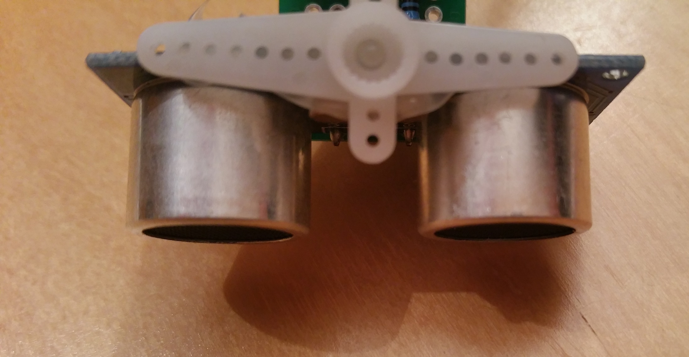
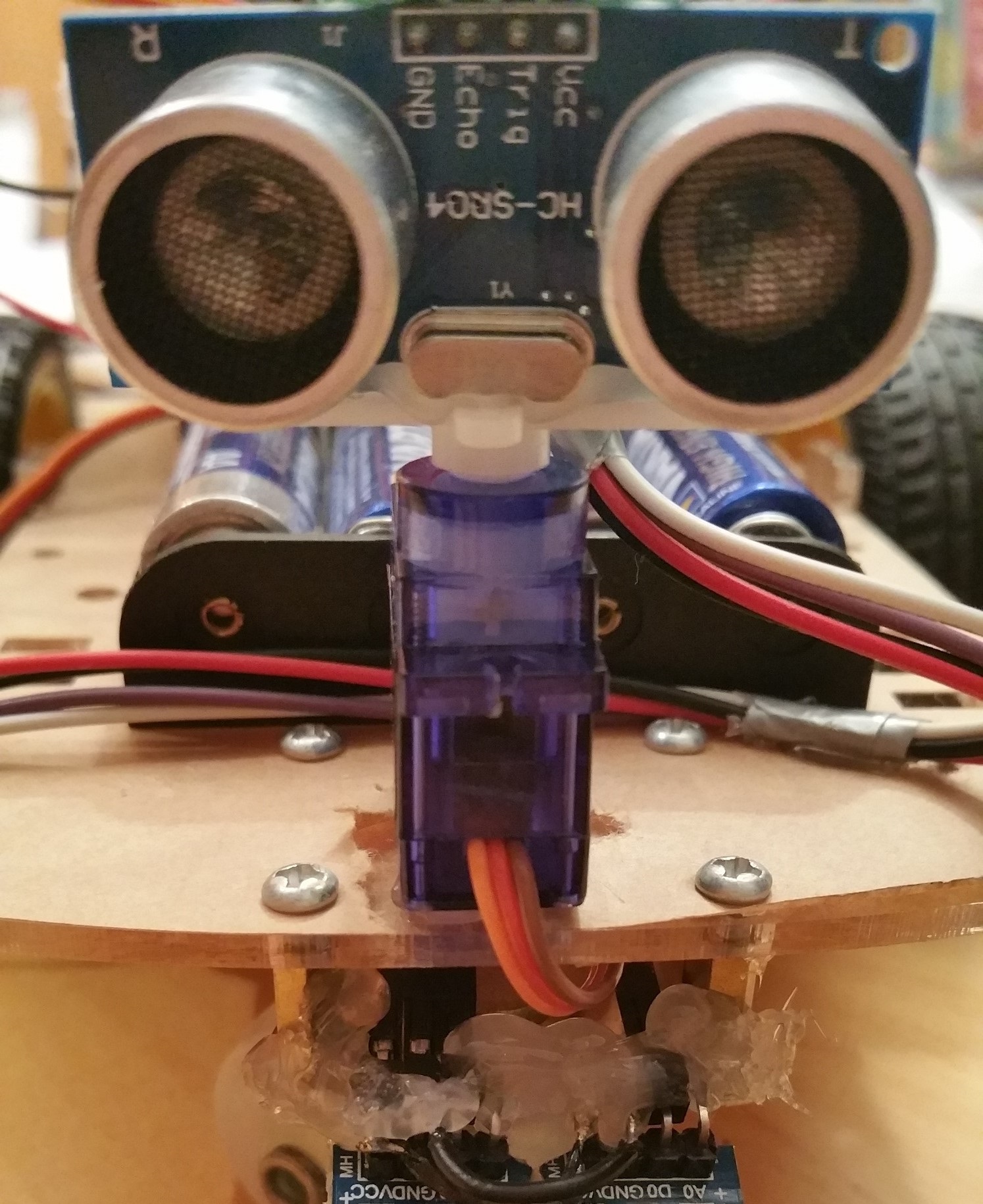
Before we proceed with the connection, we need to attach the two modules to the robot body. For this, we use the hot glue, with which we first attach the servo motor to the front (above the front wheel and in front of the IR line-follow sensors). My body had a paper cover over the plastic, which I removed from the area to be glued so that the glue sticks better.
Then I took one of the attachments of the servo motor and attached the HC-SR04 module to it with hot glue (see pictures). The attachment can also be easily attached to the motor and removed again. You can run the cables of the servo on the lower side of the body to the Pi (there is a hole in the middle). I glued the jumper cables from the ultrasonic sensor together and fixed them in one place with a little space. However, you should wait until we test the functionality and thus find the best position for the cables.

Construction and Wiring
In the previous tutorials, we have already occupied some of the GPIOs with the previous modules. For this tutorial, however, we only need three additional GPIOs, whereby I am using GPIO12, 13 (US sensor) and 22 (servo). If you want to use other IO pins, you have to adapt this accordingly later in the code.
The ultrasound module is supplied with power via the 5V of the Pi, whereas the servo motor should be connected via the batteries. Ground of the Raspberry Pi and the batteries are (as before) still connected to each other.
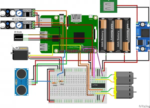
The ultrasonic sensor (ECHO) is connected to GPIO13 via a 330Ω resistor and also to GND via a 10kΩ resistor. I have already described the exact functionality of the US sensor in a previous tutorial. The same applies to the use of the servomotor via PWM. You can find details on both modules in the corresponding tutorials.
Expand Raspberry Pi Robot Code
In order to be able to measure distances from different directions in the following, we create a new file in which we define a class for the movable ultrasound module:
sudo nano ultrasonic.py
The class has only a few functions (for rotating and measuring) and is therefore not too long:
|
1 2 3 4 5 6 7 8 9 10 11 12 13 14 15 16 17 18 19 20 21 22 23 24 25 26 27 28 29 30 31 32 33 34 35 36 37 38 39 40 41 42 43 44 45 46 47 48 49 50 51 52 53 54 55 56 57 58 59 60 61 62 63 64 65 |
import RPi.GPIO as GPIO import time class US(): def rotate(self, angle): duty = float(angle) / 9.0 + 2.5 self.pwm.ChangeDutyCycle(duty) def distance(self): GPIO.output(self.triggerPin, True) time.sleep(0.00001) GPIO.output(self.triggerPin, False) start = time.time() stop = time.time() while GPIO.input(self.echoPin) == 0: start = time.time() while GPIO.input(self.echoPin) == 1: stop = time.time() #GPIO.wait_for_edge(self.echoPin, GPIO.BOTH, timeout=100) stop = time.time() return ((stop - start) * 34300.0) / 2.0 def findBestWay(self): # returns the angle where to go next func = reversed if self.rev else list arr = [0] * self.steps for i in func(range(self.steps)): #print(i * 180.0 / (self.steps-1)) self.rotate(i * 180.0 / (self.steps-1)) time.sleep(0.2) arr[i] = self.distance() # dist > 500cm or dist < 5cm means that a timeout occured => value wrong if arr[i] > 500 or arr[i] < 5: for j in range(3): arr[i] = self.distance() if arr[i] < 500 and arr[i] > 5: break else: arr[i] = -1 self.rev = not self.rev return arr def findWay(self, actualIndex): dist = self.distance() def __init__(self, servoPin = 22, triggerPin = 12, echoPin = 13): GPIO.setwarnings(False) GPIO.setmode(GPIO.BCM) # save vars self.echoPin = echoPin self.triggerPin = triggerPin GPIO.setup(self.echoPin, GPIO.IN) GPIO.setup(self.triggerPin, GPIO.OUT) # init servo self.servoPin = servoPin GPIO.setup(self.servoPin, GPIO.OUT) self.pwm = GPIO.PWM(servoPin, 100) self.pwm.start(5) self.steps = 7 # should be odd self.rev = False # set servo on 90 degree (mid) self.rotate(90) time.sleep(0.5) |
As always, the editor is saved with CTRL + O and closed with CTRL + X.
Before we continue, we want to position the ultrasonic sensor correctly. To do this, you can open the Python console as a test (sudo python) and enter the following lines (close with exit()):
|
1 2 3 |
from ultrasonic import US modul = US() modul.rotate(90) |
We let the servo motor rotate by 90° and now fix the ultrasonic module in the middle of the servo motor so that the “eyes” look straight ahead. We do this because the motor will rotate 90° to the left and right and measure the distances to which we then let the robot react.
Then we have to extend our previous robot.py file. To do this, we first import the class we just created:
|
1 |
from ultrasonic import US |
In addition, the class must be initialized. In the robot.py file, we add the parameters of the __init__ function and add a line so that the function looks like this:
|
1 2 3 4 5 6 7 8 9 10 11 12 13 14 |
def __init__(self, motor_left_pin1=17, motor_left_pin2=27, motor_right_pin1=23, motor_right_pin2=24, line_follow_pin_left=19, line_follow_pin_right=6, servo_pin=22, us_trigger_pin=12, us_echo_pin=13 ): GPIO.setmode(GPIO.BCM) GPIO.setwarnings(False) # init modules self.ultrasonic = US(servo_pin, us_trigger_pin, us_echo_pin) self.motor = L293D(motor_left_pin1, motor_left_pin2, motor_right_pin1, motor_right_pin2) self.line_follow_pin_left = line_follow_pin_left self.line_follow_pin_right = line_follow_pin_right GPIO.setup(self.line_follow_pin_left, GPIO.IN) GPIO.setup(self.line_follow_pin_right, GPIO.IN) |
Now we can add the function that reacts to the measured distances and controls the robot accordingly at the end of our Robot-class:
|
1 2 3 4 5 6 7 8 9 10 11 12 13 14 15 16 17 18 19 20 21 22 23 24 25 26 27 28 29 |
def autoPilotUSon(self): actualIndex = int(self.ultrasonic.steps / 2) degreePerStep = 180.0 / (self.ultrasonic.steps-1) while True: dists = self.ultrasonic.findBestWay() print(dists) maxIndex = dists.index(max(dists)) steps = abs(90.0 - maxIndex * degreePerStep) / degreePerStep + 1 # if distance is more than 500cm, the measurement is probably wrong -> stop if dists[maxIndex] > self.motor.DIST_PER_SEC / 2:# and dists[maxIndex] < 500: if maxIndex == int(self.ultrasonic.steps / 2): # straight forward self.motor.forward() elif maxIndex < int(self.ultrasonic.steps / 2): # turn right self.motor.forwardLeft() time.sleep(self.motor.SEC_PER_TURN / 360.0 * degreePerStep * steps) self.motor.forward() elif maxIndex > int(self.ultrasonic.steps / 2): # turn left self.motor.forwardRight() time.sleep(self.motor.SEC_PER_TURN / 360.0 * degreePerStep * steps) self.motor.forward() actualIndex = maxIndex else: print(dists[maxIndex], self.motor.DIST_PER_SEC) self.motor.stop() return |
Testing the Autopilot
It is time to test the autopilot mode, which is why we are creating a small test file in which the robot class is loaded and the ultrasonic autopilot is started:
sudo nano test_us.py
The file only contains the following content:
|
1 2 3 4 5 6 7 8 |
from robot import Robot import time try: r=Robot() r.autoPilotUSon() except: r.motor.stop() |
After the file has been saved, we place the robot on the floor and call the Python file from the console (can be canceled with CTRL + C):
sudo python test_us.py
Important: If your robot turns too fast or too slowly, it is most likely due to an incorrectly set speed. In the first tutorial in the series, we have already mentioned defines the speed on a straight line (DIST_PER_SEC) and for a rotation (SEC_PER_TURN). However, since this depends on the substrate, it may have to be adjusted. I had e.g. during testing, the speed was measured on the table, but it differs from the actual speed on the floor, which is why the functions were only able to work properly after an adjustment.
It continues with following your own voice.