
LCD character displays are a simple and a cost-effective way to display a text. Thanks to the HD44780 controller, the control of the modules has become very simple. However, one must occupy many GPIOs for it. An alternative is the I2C data bus, which means that only two GPIOs are used.
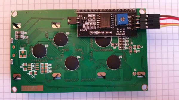
In this tutorial a 20×04 HD44780 character display is controlled using a I2C display adapter. A logic converter is used to adjusting the voltage level for the module without damaging GPIOs.
Accessories
In order to access an HD47780 display via I²C, I have used the following accessories:
- 20×04 or 16×02 Character HD44780 Display (US / UK)
- I2C Display Adapter (US / UK)
- I2C Logic Level Converter (US / UK)
- Breadboard
- Jumper wire
Setup
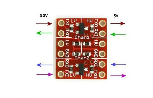
The Raspberry Pi GPIOs can not get more than 3.3V voltage, but there are some modules (like this display), which send and want to receive 5V signals. For this, a Logic Level Converter can be used, which has 2 sides. On one side those connections that are running on 3.3V are connected and on the other those with 5V. You can recognize this at different characteristics (LV – HV), as you see in the following picture:
The pins are then connected as follows:
| Raspberry Pi | 3.3V Level Converter | 5V Level Converter | I2C LCD Adapter |
|---|---|---|---|
| 3.3V (Pin 1) | LV | — | — |
| 5V (Pin 2) | — | HV | VCC |
| GND (Pin 6) | GND | GND | GND |
| GPIO2 / SDA (Pin 3) | TX1 (below) | — | — |
| GPIO3 / SCL (Pin 5) | TX1 (above) | — | — |
| — | — | TX0 (below) | SDA |
| — | — | TX0 (above) | SCL |
Here is a schematic drawing:
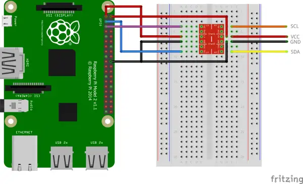
Any ground pin can be taken. For the sake of clarity, I chose pin 20 instead of pin 6 on the schematic diagram.
This configuration is also usable with other modules which require signals with a higher voltage than 3.3V (in this case 5V) (real time clock, etc.).
Software
Before we can start, two I²C tools are needed, which we install:
sudo apt-get install python-smbus i2c-tools
Then we will release I2C (if you have already released it from previous tutorials, you can skip it):
sudo raspi-config
Under “Interfacing Options”> “I2C” we activate it. Now add the corresponding entries to the modules file:
sudo nano /etc/modules
These two lines are added to the end:
|
1 2 |
i2c-bcm2708 i2c-dev |
Afterwards it has to be restarted, so that all changes take effect.
sudo reboot
If you have already connected the display, you can now test whether it has been detected (if you have one of the first Raspberry Pi’s [Rev.1], you have to pass 0 instead of 1):
sudo i2cdetect -y 1
The output should look like this:
pi@raspberrypi ~ $ sudo i2cdetect -y 1
     0  1  2  3  4  5  6  7  8  9  a  b  c  d  e  f
00:          -- -- -- -- -- -- -- -- -- -- -- -- --
10: -- -- -- -- -- -- -- -- -- -- -- -- -- -- -- --
20: -- -- -- -- -- -- -- 27 -- -- -- -- -- -- -- --
30: -- -- -- -- -- -- -- -- -- -- -- -- -- -- -- --
40: -- -- -- -- -- -- -- -- -- -- -- -- -- -- -- --
50: -- -- -- -- -- -- -- -- -- -- -- -- -- -- -- --
60: -- -- -- -- -- -- -- -- -- -- -- -- -- -- -- --
70: -- -- -- -- -- -- -- --
If you see a number other than 27, you must change this in the lcddriver.py file (ADDRESS = 0x27).
Let’s start with the code:
mkdir hd44780 && cd hd44780
wget http://tutorials-raspberrypi.de/wp-content/uploads/scripts/hd44780_i2c.zip
unzip hd44780_i2c.zip
With the help of the two included scripts, the display can now be addressed. To do this, we open the Python console and enter the following code:
sudo python
|
1 2 3 4 5 6 7 8 9 10 |
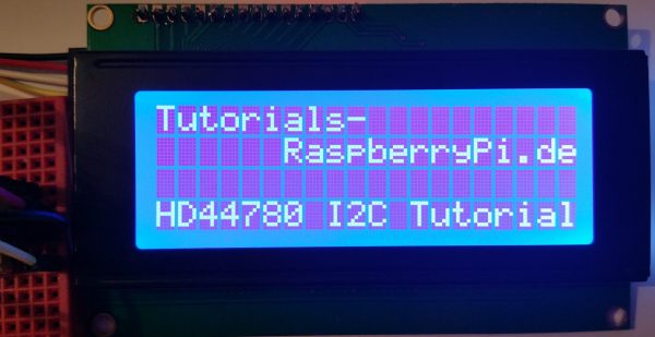
import lcddriver from time import * lcd = lcddriver.lcd() lcd.lcd_clear() lcd.lcd_display_string("Tutorials-", 1) lcd.lcd_display_string(" RaspberryPi.de", 2) lcd.lcd_display_string("", 3) lcd.lcd_display_string("HD44780 I2C Tutorial", 4) |
The first parameter of the lcd_display_string is for the text and the second for the row. You do not have to change all lines at once, but you can not easily replace individual characters. For this, the entire text (with the character changed at the desired position) would have to be retransmitted.
The contrast of my I2C adapter was at the beginning very low. If nothing should be shown, test the wheel on the back and look obliquely on the display.
Code Reference: https://github.com/CaptainStouf/raspberry_lcd4x20_I2C
18 Comments
This is very unique and interesting information. Logical level converters have played and important role in advanced science and novel technology. Thanks for sharing this with us. Kindly post more informative content like this.
You are welcome 🙂
Perfect tutorial.
Is there a simple way to displaying sensor data on the web?
Best regards and thank you very much for such a good useful and interesting tutorial.
You could use a Node.JS Server: How to setup a Raspberry Pi Node.js Webserver and control GPIOs
I don’t understand how this works!
I2C is a bi-directional interface, but your level shifters are uni-directional.
Have I missed something???
(Ok, my bad n sorry about the spam. The level shifter is bi-directional. Whatever next…)
Forgive me if this is a dumb question, but, how do you get the val of hx711 example.py to the LCD screen? Does this code need to be inserted somewhere inside of example.py? What format would one use in the lcd.lcd_display_string(“??????????”,1)?
I was stuck on there too! Took me lots of logical thinking to figure it out and I’m glad I can share the knowledge 😀
You have to do a few things. First, let’s look at the file organisation. When you run the code it will look for the LCD library. You would have downloaded the hd44780 folder as described above I’m assuming. Once this is done copy paste all the files from the hd44780 folder into the HX7411 folder. Now when you run your code everything will be in the folder it’s looking for any libraries that you import in the code.
Next step is to copy some of the code you used above in this tutorial to make all of your hearts desires(in word and number form obvz) appear on your LCD.
I’m going to assume you can figure out what you need at the beginning of your code as it’s pretty much the same as the code in this tutorial sans the ‘from time import * ‘ command which wasn’t needed for some reason. I don’t know that is or have bothered to look, but would love it if someone could eloquently explain it here 😀
The part that tested my brain powers was displaying the value later in the code(as I am but a very simple hobby coder). After the ‘print val’ command you need to add these 2 lines, which will display some words and the weight. (the order doesn’t actually matter just put it within the while true try)
lcd.lcd_display_string(“Yo mamma weighs:”, 1)
lcd.lcd_display_string(‘%s’,%val, 2)
how the second line works is shown here:
https://www.raspberrypi.org/forums/viewtopic.php?t=154414
So that’s pretty much it. Hope this helps 😀
Please feel free to correct my terminology in this post all you lovely community grammar/coder lovers.
pi@raspberrypi:~ $ sudo i2cdetect -y 1
0 1 2 3 4 5 6 7 8 9 a b c d e f
00: — — — — — — — — — — — — —
10: — — — — — — — — — — — — — — — —
20: — — — — — — — — — — — — — — — —
30: — — — — — — — — — — — — — — — —
40: — — — — — — — — — — — — — — — —
50: — — — — — — — — — — — — — — — —
60: — — — — — — — — — — — — — — — —
70: — — — — — — — —
In test not show 27 or other number….
which numberi use in address
I am reading some data from the sensor and storing it in some variable called “Mydata”. Now, my question is how to display that Variable “Mydata” to the LCD display. Also, the Variable is changing frequently, will the change reflect in the LCD automatically?
Hi,
thanks for the tutorial. Is it possible to print custome characters to the display?
I have connected a “GROVE-LCD RGB Backlight v4.0” display to a “Raspberry PI 3 Model B” directly. I think the PIN 2 can server 5V. Hence I have connected the display directly with the PI. i2cdetect outout is as follows. But when I am sending any msg to the display, it is not displaying. Can you please help to identify the issue?
pi@raspberrypi:~/Documents $ sudo i2cdetect -y 1
0 1 2 3 4 5 6 7 8 9 a b c d e f
00: 03 — — — — — — — — — — — —
10: — — — — — — — — — — — — — — — —
20: — — — — — — — — — — — — — — — —
30: — — — — — — — — — — — — — — 3e —
40: — — — — — — — — — — — — — — — —
50: — — — — — — — — — — — — — — — —
60: — — 62 — — — — — — — — — — — — —
70: 70 — — — — — — —
pi@raspberrypi:~/Documents $
If you are running this project on a Pi-1, you also need to edit i2c_lib.py so this line:
def __init__(self,addr,port=1)
is changed to
def __init__(self.addr,port=0)
Hello, am a bit late to this but got it all working as showed and got some display lines to change but very dumb question im sure…. when trying to load the command into my terminal from my saved python file it comes up saying ” cant find ‘_main_’ module in lcd. what am i doing wrong?
Are you saying you can’t run this program from the python command line? Or that you’re trying to write to the LCD from the command line?
There is no need for a ‘level converter’ for the I2C signals as true I2C devices use ‘open collector’ drivers. All one needs to do is remove the 4K7 resistors attached to the SDA and SCL lines on the LCD I2C adapter and everything will work perfectly. The I2C chip on the adapter will accept the 3.3V SDA and SCL signals from the RasPi without any problems and the ‘open collector’ driver on the adapter’s SDA signal will act as it should by simply pulling the SDA signal to ground.
There are 1.8k pull ups on the PI to 3.3V. If you read the data sheet for the PCF8547 it states that the minimum high input voltage is 0.7VDD and if VDD is 5V that would be 3.5V. I believe that it may work at 3.3V but that is not within the spec range. The 4.7k pull ups to 5V on the converter board will combine with the 1.8k resistors and 3.3V supply on the Pi to produce a thevenin equivalent pull up 1.41k to 3.77V. If there are protection diodes on the SDA and SCL outputs on the PI, and assuming their forward voltage is 0.3V, then there would only be 120uA of current flowing in the diode. Changing the pull ups on the converter board to 10k provides a thevenin equivalent pull up of 1.525k to 3.56V which is within the spec range (barely) and the high level would be less than 0.3V above 3.3V. To place the pull up voltage at 3.6V an 8.2k resistor would be about right for the pull up on the converter board.