
With the ESP32 Cam, there is a cheap and compact alternative to the common IP cameras that are usually used for surveillance. This means that you can either set up a live stream and watch it permanently or, for example, record and save regular still images (wild camera).
The ESP can also be used for other projects at the same time, as many IO pins are still free. In this tutorial, we look at the necessary steps to do it and flash the ESP32 Cam software. Then we configure the camera and create a live stream that can be integrated into various smart home systems and accessed from a smartphone.
Required Hardware Parts
Anyone who has an ESP8266 with enough pins can theoretically take and connect an OV2640 or OV7670. However, this is advantageous in the rarest cases, as this is more work and becomes more expensive in most cases. However, there is already combined modules (ESP32 + Camera) for little money. Nothing has to be soldered here and you can start directly. Only a serial USB adapter is needed.
I have used the following components:
- ESP32 camera module (combined)
- FT232RL adapter (USB to TTL)
- Female-female jumper cable
There are also sets with all parts to buy, but some hobbyists will have jumper cables and a USB-TTL adapter lying around anyway.
Connection and Cabling of the ESP32 Cam via Serial USB Port
In contrast to the NodeMCU Development Board, the ESP32 module with a camera does not have a USB port and must therefore be connected to the computer via an adapter. We use the red FT232 USB-TTL serial adapter for this. This can deliver 3.3V or 5V voltage. Make sure the jumper is set to 5V. From above, the ESP board looks like this:
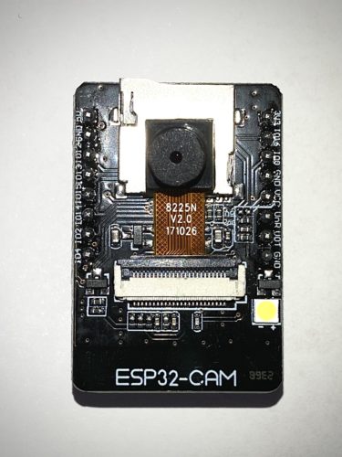
Incidentally, the camera is very easy to assemble. All you have to do is open the bracket 90° and insert the end of the ribbon cable. Then we close the bracket again and the small camera is attached.
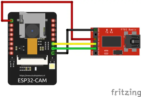
The wiring to the serial USB adapter is as follows:
| ESP32 Cam Modul | FT232 USB-TTL Serial Adapter |
|---|---|
| 5V | VCC (5V) |
| UOR | Tx |
| UOT | Rx |
| GND | GND |
Here you can see the whole thing again as a schematic structure:
 Now you can connect the FT232 adapter to your computer. A new device should have been recognized immediately.
Adapt and Flash ESP32 Cam Code
If you have not yet flashed an ESP8266 with the Arduino IDE, you should first take a look at this tutorial, which explains the basics.
ESP8266: Install the Arduino IDE for the ESP32
- In the Arduino IDE we navigate to Preferences> Additional Board Manager URLs and add the following (two links separated by commas):
https://dl.espressif.com/dl/package_esp32_index.json, http://arduino.esp8266.com/stable/package_esp8266com_index.json
- Then we switch to Tools> Board> Board Manager and install “ESP32 by Espressif Systems” (search for ESP32).
- Last but not least, we select this board under Tools> Board: DOIT ESP32 DEVKIT V1. Under Tools> Port you should also see where the ESP is connected (e.g. COM11).
We are now ready to transmit our code. There is already a ready-made sample project for this, which sets up a camera server on the NodeMCU. You can import the project as follows:
File > Examples > ESP32 > Camera > CameraWebServer
We have to adjust a few lines here. First of all #define CAMERA_MODEL_WROVER_KIT has to be commented out with two slashes (//) and #define CAMERA_MODEL_AI_THINKER has to be commented in again:
//#define CAMERA_MODEL_WROVER_KIT
#define CAMERA_MODEL_AI_THINKER
Finally, the values for ssid (name of your WiFi network) and password have to be adjusted. Then you can compile the code (check mark/verify) and then upload it to the connected ESP32.
First Test of the Camera
As soon as the upload was successful, you can open the serial monitor (under Tools). If nothing is visible here, you can restart the ESP with the reset button (RST) on the back. You will then see the following screen:
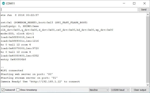 The internal IP address is visible at the end (192.168.1.12 in my case). We enter this IP in the browser of another device that is in the same network.
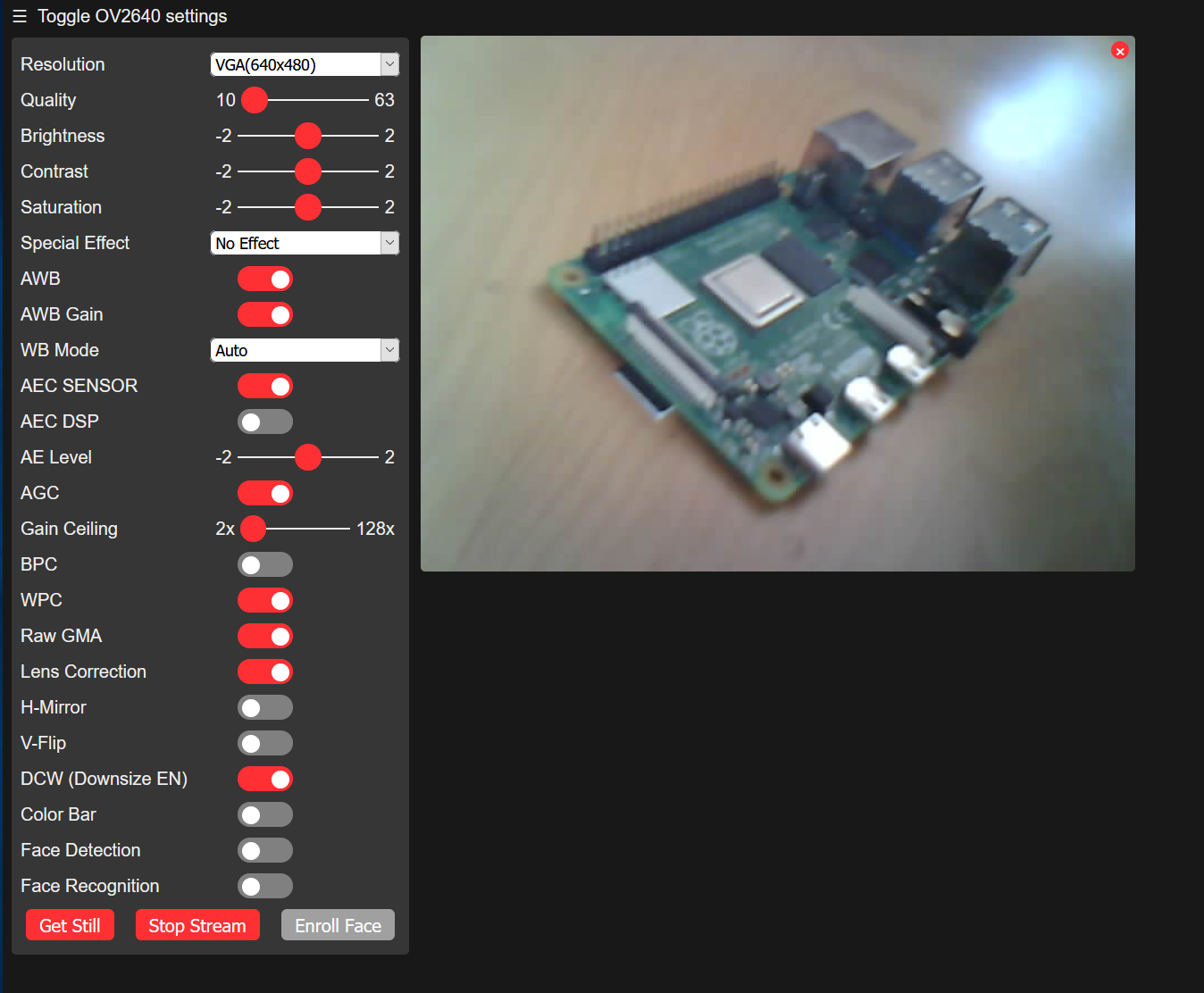
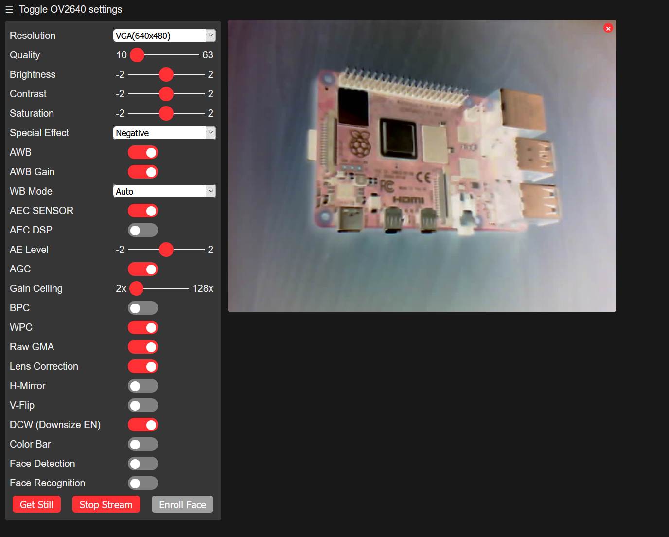
Many options are now visible on the left. For example, we can adjust the resolution (a higher resolution leads to a lower frame rate). Of course, brightness, contrast, saturation and many other options can be set. This is still possible while the stream is already running.
Now click on “Start Stream”, after which you will see a live preview of the camera on the right:
For example, if you want to see contrasts better or the settings are too dark, you can also display the negative image, like I did with a Raspberry Pi:
By the way: All of these settings can also be set using the REST API. For this purpose, a GET of the /control endpoint with the corresponding query parameters is sent. The easiest way to find out the individual parameters is to use the developer tools in your browser (F12).
Remove infrared filter: night shots/wildlife camera
The camera, which is included, has an infrared filter built-in, like most cameras (not the NoIR Raspberry Pi camera). This means that a little less light reaches the lens, which is why little can be seen, especially in dark scenes. However, this IR filter can also be removed, which means that more can be seen when taking pictures at dusk. How to remove the infrared filter and what to watch out for is described in more detail here.
Integrate ESP8266 Camera Live Stream (Smart Home Systems)
After we have adjusted our camera settings so far, we would also like to integrate the stream into other applications. The practical thing is that the stream is sent in MJPEG format (updating a single image). This means that it can be integrated into websites using the <img /> HTML tag, for example. The link of the stream is under port 80 under the address /stream (in my case http://192.168.1.12:81/stream).
This means that the live stream can also be integrated into smart home systems such as OpenHAB. Let’s look at this in the following example.
First of all, we need a sitemap. Our image stream then comes into this. With this you can create a new file via the terminal:
sudo nano /etc/openhab2/sitemaps/cameras.sitemap
The file has the following content:
sitemap demo label="Camera Livestreams" {
    Frame label="Demo" {
        Image url="http://192.168.1.12:81/stream" label="Livestream Garden"
    }
}
You can then save the file with CTRL + O. Now you can see the stream in your OpenHAB dashboard. In the same way, we can also include videos, maps, etc. in the overview.
1 Comment
this is all new to me ..I got my esp32 to stream on my windows 10 desktop and now I would like to do the same as this article describes with My Pi3model B…So must 1st install the Arduino Ide on the Pi? It seems like a different install than the one prior? or do you just simply pick the 1st linux option? Thanks for any clues LOL