
One of the many Raspberry Pi projects is the lighting of rooms or objects. LED strips are particularly suitable for this purpose, because many individual LEDs are aligned and each individual LED can display all RGB colors. Thus, some projects such as room lighting, Ambilight or e.g. a Christmas tree lighting can be realized. The effects of the colorful lights are impressive.
This article shows the general usage of the WS2801B on the Raspberry Pi. In doing so, we create an example in which LEDs of the strip are set (rainbow colors) and the brightness is dimmed. In the video at the end of the tutorial you can see the whole thing in action.
Equipment
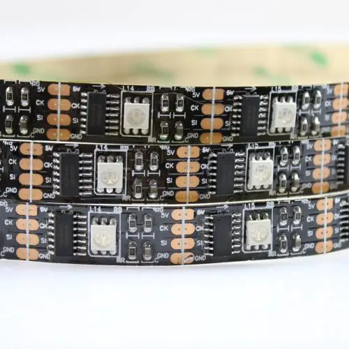
The RGB LED strips require an input voltage of 5V. The most favorable variant with 32 LEDs per meter has a distance between the LEDs of only 2.5 cm:
There are also versions available that are dust and water-resistant (IP67). Each of the individual LEDs has a current consumption of about 60 mA. At one meter this is almost 2A. This is quite more than the GPIOs of Raspberry Pi can deliver. We therefore need an external current source that supplies power to the RGB stripe. Depending on how long your strip is, the maximum current must be higher. The power supply should therefore be able to supply 10A at 5 meters.
You have the choice between two possibilities:
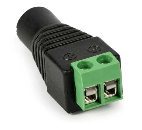
- For beginners: Power adapter (US / UK) + plug-in connector (US / UK) (c.f. picture on the right)
- For experienced: Switching power supply (US / UK) + power cord (US / UK)
The difference is that a power cable has to be disconnected and then connected to the switching power supply. Since working with high voltage is dangerous, this is not recommended for beginners. For a power supply (similar to the laptop chargers) you only need an additional Power Jack adapter, so that you can detach the two voltage poles.
Last but not least jumper cables and a breadboard (US | UK) are required.
WS2801B vs. WS2812B
The WS2812 LED strips are often found on the Internet, which are also somewhat cheaper than the WS2801 models. However, these are not all too good for the Raspberry Pi, since the onboard audio output of the Raspberry Pi can not be used anymore. However, I will write another tutorialon how to use the WS2812 LED strips.
WS2801B strips have two data lines (data and clock), whereby individual LEDs can be addressed via the integrated SPI bus of the Raspberry Pi. This is different for the WS2812B models. These strips have only a single data pin, which is why before sending a lot more has to be calculated. For this reason the WS2801B RGB LED strips are preferable to the WS2812 for use on the Raspberry Pi, despite their supposedly smaller “serial number”.
Connect the switching power supply to the WS2801
Before we start, we have to connect the current source (only for the plug-in power supply). If you have selected the first variant – a charger-like power supply – you can jump to the next point. You only need to clamp the plug adapter to the power supply and loosen the screws.

First of all: Working with 230V voltage can be deadly! While you make changes, all connections to the socket must be disconnected! Be careful and only work with it if you are sure of your cause. If this is not the case, I recommend the first power supply.
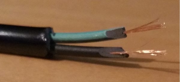
We start by cutting the power cord (e.g. old PC power cable). There are two or three cables inside. These must be carefully separated by about 1cm from the insulation, so that only the wire is visible in the cables. The switching power supply has three connections on the left side. On the one hand, “L” (phase / outer conductor) and “N” (neutral conductor), which are marked with AC (alternating current) and a grounding symbol. If your cable only contains two smaller cables, they will be connected to the AC connectors. If there are three, you must also identify the earth cable and connect it to the earthing symbol / “PE” connector.
Since the colors of the inner cables differ with older power cables, here is a brief overview, what color comes:
- The black or brown cable comes to the outer conductor “L“.
- The blue cable is connected to the neutral conductor “N“.
- The green-yellow cable is connected to the protective conductor “PE” or grounding symbol.
For connecting the cables, the screws of the power supply must be loosened. Then place the wires under the screws. Make sure that they are well screwed and that the cables can not come loose. Normally, these devices still have a small protective flap, so that you don’t touch them accidentally. If you want to be safe, you can also wrap insulation tape around the sensitive spots.
On the other side, there are outgoing 5V voltage (+V) and the ground connections (-V or COM). As a test, you can use a Multimeter to measure the voltage as shown here:

Wiring between Raspberry Pi, WS2801 and current source
Normally, the LED strips come with soldered plugs, which are intended for connecting several WS2801 strips. In addition, there is usually also a plug, which can be put on a Breadboard (4 connected cables). Furthermore, two additional cables for the external power connection from the LED Strip (red and black) are often used.
Since the color of the cable does not necessarily correspond to the standards, you should pay attention exactly which cable leads to which connection on the strip. Incorrect wiring on the Raspberry Pi could result in overheating or a short-circuit.
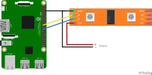
If you are aware of which cable leads to which connection, we can connect it. The Raspberry Pi should be switched off and the switching power supply should not be connected to the socket. The cables are connected as follows:
| WS2801 LED Stripe | Raspberry Pi | (Switching-) Power Supply |
|---|---|---|
| 5V | — | +V |
| CK / CI | Pin 23 (SCKL) | — |
| SI / DI | Pin 19 (MOSI) | — |
| GND | Pin 6 (GND) | -V or COM |
For the connection to the switching power supply you can also use the two additional cables (if available). It is important that GND / ground is connected to both the Raspberry Pi and the external power supply. The structure now looks as follows:
Installing the Raspberry Pi WS2801 RGB LED Library
To control the LED strip we use a Python library from Adafruit. This special Raspberry Pi WS2801 library includes some functions for controlling the individual LEDs. The good thing is that each LED can be addressed individually and any RGB color is possible.
The library requires the SPI bus, which we have to activate (if not already done). We call the following:
sudo raspi-config
Under “Advanced Option” there is a point for “SPI”. We enable it and exit the configuration menu.
The installation now works quite simply via the Python package manager from the normal console / terminal. Preventively, we are first updating the package sources and installing PIP (this is not included on the Raspbian Lite versions by default):
sudo apt-get update
sudo apt-get install python-pip -y
sudo pip install adafruit-ws2801
If you have a lite version or SpiDev is not installed on your system, please follow this guide to install and activate it. On newer Raspbian versions, however, it should already be pre-installed.
Since the given example of the developers apparently does not work on all (fresh) Raspbian versions, I have changed that and expanded.
Sample code for brightness dimming of the WS2801 LEDs
The following example can be used and extended for your own projects. Here, a few colors (rainbows) are first switched in series, whereupon the brightness of the individual colors is dimmed. For this, it must be said that the brightness of a color can also be defined with the RGB value (see RGB Color Picker for this).
So let’s create a file:
sudo nano ws2801_example.py
The following content should be inserted:
|
1 2 3 4 5 6 7 8 9 10 11 12 13 14 15 16 17 18 19 20 21 22 23 24 25 26 27 28 29 30 31 32 33 34 35 36 37 38 39 40 41 42 43 44 45 46 47 48 49 50 51 52 53 54 55 56 57 58 59 60 61 62 63 64 65 66 67 68 69 70 71 72 73 74 75 76 77 78 79 80 81 82 83 84 85 86 87 88 89 90 91 92 93 94 95 96 97 98 99 100 101 102 103 104 105 106 107 108 109 110 111 112 113 114 115 116 117 118 119 120 121 |
# Simple demo of of the WS2801/SPI-like addressable RGB LED lights. import time import RPi.GPIO as GPIO # Import the WS2801 module. import Adafruit_WS2801 import Adafruit_GPIO.SPI as SPI # Configure the count of pixels: PIXEL_COUNT = 32 # Alternatively specify a hardware SPI connection on /dev/spidev0.0: SPI_PORT = 0 SPI_DEVICE = 0 pixels = Adafruit_WS2801.WS2801Pixels(PIXEL_COUNT, spi=SPI.SpiDev(SPI_PORT, SPI_DEVICE), gpio=GPIO) # Define the wheel function to interpolate between different hues. def wheel(pos): if pos < 85: return Adafruit_WS2801.RGB_to_color(pos * 3, 255 - pos * 3, 0) elif pos < 170: pos -= 85 return Adafruit_WS2801.RGB_to_color(255 - pos * 3, 0, pos * 3) else: pos -= 170 return Adafruit_WS2801.RGB_to_color(0, pos * 3, 255 - pos * 3) # Define rainbow cycle function to do a cycle of all hues. def rainbow_cycle_successive(pixels, wait=0.1): for i in range(pixels.count()): # tricky math! we use each pixel as a fraction of the full 96-color wheel # (thats the i / strip.numPixels() part) # Then add in j which makes the colors go around per pixel # the % 96 is to make the wheel cycle around pixels.set_pixel(i, wheel(((i * 256 // pixels.count())) % 256) ) pixels.show() if wait > 0: time.sleep(wait) def rainbow_cycle(pixels, wait=0.005): for j in range(256): # one cycle of all 256 colors in the wheel for i in range(pixels.count()): pixels.set_pixel(i, wheel(((i * 256 // pixels.count()) + j) % 256) ) pixels.show() if wait > 0: time.sleep(wait) def rainbow_colors(pixels, wait=0.05): for j in range(256): # one cycle of all 256 colors in the wheel for i in range(pixels.count()): pixels.set_pixel(i, wheel(((256 // pixels.count() + j)) % 256) ) pixels.show() if wait > 0: time.sleep(wait) def brightness_decrease(pixels, wait=0.01, step=1): for j in range(int(256 // step)): for i in range(pixels.count()): r, g, b = pixels.get_pixel_rgb(i) r = int(max(0, r - step)) g = int(max(0, g - step)) b = int(max(0, b - step)) pixels.set_pixel(i, Adafruit_WS2801.RGB_to_color( r, g, b )) pixels.show() if wait > 0: time.sleep(wait) def blink_color(pixels, blink_times=5, wait=0.5, color=(255,0,0)): for i in range(blink_times): # blink two times, then wait pixels.clear() for j in range(2): for k in range(pixels.count()): pixels.set_pixel(k, Adafruit_WS2801.RGB_to_color( color[0], color[1], color[2] )) pixels.show() time.sleep(0.08) pixels.clear() pixels.show() time.sleep(0.08) time.sleep(wait) def appear_from_back(pixels, color=(255, 0, 0)): pos = 0 for i in range(pixels.count()): for j in reversed(range(i, pixels.count())): pixels.clear() # first set all pixels at the begin for k in range(i): pixels.set_pixel(k, Adafruit_WS2801.RGB_to_color( color[0], color[1], color[2] )) # set then the pixel at position j pixels.set_pixel(j, Adafruit_WS2801.RGB_to_color( color[0], color[1], color[2] )) pixels.show() time.sleep(0.02) if __name__ == "__main__": # Clear all the pixels to turn them off. pixels.clear() pixels.show() # Make sure to call show() after changing any pixels! rainbow_cycle_successive(pixels, wait=0.1) rainbow_cycle(pixels, wait=0.01) brightness_decrease(pixels) appear_from_back(pixels) for i in range(3): blink_color(pixels, blink_times = 1, color=(255, 0, 0)) blink_color(pixels, blink_times = 1, color=(0, 255, 0)) blink_color(pixels, blink_times = 1, color=(0, 0, 255)) rainbow_colors(pixels) brightness_decrease(pixels) |
In line 11 you have to specify the number of LEDs that are on the connected strip. This should be 32 meters. You can save the file with CTRL + O and close the editor with CTRL + X.
Here is the promised video with the different effects from the file:
I would be interested in what projects do you plan to do (Advent lighting, Christmas tree decoration, spice up rooms, “Infinite Mirror Table”, etc.)? Are there any requests for specific tutorials related to the Raspberry Pi WS2801B controller? I already have some ideas, but would also like to hear your opinion 🙂
88 Comments
Hi guys, firstly well done getting your LED strip to work. Now I have spent days (literally ) looking at websites, level convertors, multimeter test, circuits and rxtx libraries, software like Glediator the whole kaboodle. The wife will raise eyebrows at the paypal account I can tell you. Currently trying to run a WS2801 strip with 160 rgb leds and if i’m lucky i’ll get three to light up. Is there a forum that will help me step by step?
Are you sure that is a WS2801? Can you contol any of those 3?
I’m in the same boat – did you ever get yours working? And any tips or links to get going? Using this tutorial with the 5meter strip is not working quite as easily…. anyway, if anyone else finds this in the future, https://raspberrypi.stackexchange.com/ is the place to check next.
Thanks for that great tutorial! I reconstructed it. Do you have by any chance another one explaining how to use the music input with the WS2801?
Hello !
Nice work, can we use this setup to create an ambilight like for TV and HDMI Sources ?
if Yes, I am noobie, would love to have a tutorial !!!
Thanks
Yes, I have done that already (german site), but not translated yet.
Awesome, I can translate the website !
Thanks for your answer.
Is it possible to do ambilight for HD sources with a WS2812B only using a Rapsberry pie 3 and Hyperion (without adruino)? This way, I can use the WS2801 tutorial you did (if it’s exactly the same steps), using my WS2801B.
Thanks for the awesome work !
Yes, I did it completely without an Arduino (but WS2801 instead of WS2812).
Ow, so the thing is : I can’t get ambilight for hdmi sources using Ws2812B without Andruino ?
If there’s any way to make my Tv look awesome like yours, I would really appreciate your help !
Thanks !!
Maybe you can, but I haven’t tried yet. If you use an external audio card, you can use the WS2812 on a Raspberry Pi (tutorial on my german site)
You can use spi with ws2812 and then onboard audio works fine.
Thanks,
I am newbie at this project… Is a Elegoo Uno (Arduino uno clone) will work ?
This is a Raspberry Pi project, so no it will not work with an Arduino 🙁
Hi Felix, thank you so much for this great guide, well explained!
I have 2 questions :
1 – If I use th “Switching power supply” solution, will it be possible to use it to power up the raspberry via tha GPIO pins (5v & Ground)? I read that if so there would not have any over current/voltage
protection? seems dangerous! (source: modmypi.com/blog/how-do-i-power-my-raspberry-pi)
2 – I’m writing a custom library in NodeJS to control the RGB strip, to reduce the size of the installation I would like to use the small Pi Zero board, The purpose is to update each led of the strip at a 50ms frequency. Do you think the GPIO bandwidth & the CPU of the Pi would handle such a frequency?
Thank you again!
Hi Bilel,
1 – it’s only an option but yes, you are wright.
2 – you have to know that the Pi does not operate in real time like an Arduino, so it could be possible, that the frequency will vary. But actually, the Pi Zero can do that (see my YT channel, where I used a Pi Zero and WS2812).
Best regards,
Felix
Thks for the quick answer Felix, the video answers my 2 questions!
Is the lack of the over current/tension protection so important?
I also seen your try with the Pi Zero is very very responsive, hope it will act the same way with a 5 meter 2801 strip xD
any idea how do i make rainbow cycle only to loop forever smoothly? thanks
nvm figured it out.
Hi, what components such as resistors did you use on your breadboard? Also, I can somewhat make out the wire connections in the video , but It’s not a precise top down view, which would of been easier. If possible is there a schematic of the wires from the pi , leds, and external power going into the breadboard slots. Would make my life a lot easier. Been trying to figure this out for months. Thanks
Just use the wiring as shown in this post.
Maybe you didn’t see what I was talking about but very clearly in the video, the one linked in this post, there are 3 resistors on the breadboard he is using. https://i.imgur.com/jH4BQJ2.jpg I just don’t know what ohm rating to get for the resistors, that’s the only thing left I need to do.
These aren’t resistors, these are diods, but I am not using them (had something else connected before and just forget to remove them).
Very cool, thanks for sharing!! I’m a newbie to all this trying to keep up with my kid. Some projects we’re looking to do together are build a sound reactive lightning simulator as well as Christmas tree lights synchronized to music (so those are my tutorial suggestions ;)).
I’m looking for a tutorial to connect multiple WS2801B strips for a Christmas lights projects using the lightshowpi project. Any luck?
Fantastic tutorial. I’m using AlexaPi and the Magic Mirror platform and will have these led’s built into the frame of the mirror. I would like these to be triggered when Alexa is summoned similar to an Echo. This would imitate the blue light moves around the Echo when it hears the trigger word. How would I program that scheme?
I’m looking to connect multiple WS2801B strips for a christmas lights project. From the research i’ve done, it seems like I need a port expander like the MCP23S17. But I couldn’t find a wiring diagram. Can you point me in the right direction? Thanks!
No you can use it with two GPIOs, as I have shown in the tutorial.
Thank you so much for the reply. I think your blog is an excellent resource for learning. I really appreciate it.
In your tutorial, you have a single long strip. I’m looking to connect 3+ strips simultaneously, use the lightshowpi project to control the lights and play music at the same time. I’ll power the three strips using three 5v-10A power supplies. Correct me if I’m wrong, but would I have to daisy chain the CK / CI Pin 23 (SCKL) and SI / DI Pin 19 (MOSI) from one strip to the next in order to achieve this?
For a switching PS….couldn’t one use a PS from a PC. I mean it has 3.5 5.0 and 12 volts…and most of easy delivers 30 amp i think i have a china RGB chain that needs 12v – but i cant really remember anyways thats not the question…the question is about he PC PS….and wouldnt you be able to draw the 5 volts for your raspberry from same PS – as far as i know – ih has 2 or 3 or sometimes 4 channels with 5 volts…..even if there was a fluktuation wich i dont think there is…the PS should swich off – isn’t that right?
Thanks in advance
Arne
You can power the Pi with 5V from the power supply, but do NEVER connect 5V to any GPIO – it will break it.
Thank you for the answer – no i wouldnt do that 🙂
I have a 12 volt 30 amp supply and I just connect a car USB charger to it in order to power my pi. I have used PC supplies in similar fashon which failed prematurely. I’ve been told they are designed to be fully loaded so leaving the other rails, 3.3v and -12v, unloaded causes it to prematurely fail (improper heat distribution stresses solder joints). Plus, some supplies have multiple 12v rails which equals the rated current so if it were rated at 35 amps, it may have two 12 volt, 15 amp rails and one 12 volt, 5 amp rail. Then again, I could just be buying cheep PC power supplies. 🙂
I have powered lots of projects from desktop psu’s there is no need to have it under load if it is a modern one then you have to bridge two of the lines to get the psu to power up I have used one to build a bench power supply which had 3.3v 5v 12 v and one adjustable output that could be adjusted for either constant current or constant voltage which I used for charging batteries with.
Great turtorials and awesome work. I went thru the ws2812 turtorial and I am stumped. I keep getting an error saying ws.ws2811_init failed with -5 (mmap(), #something I can’t remember#). Needless to say, it won’t control my light strip, 308 channels using program striptest.py. I’m a noob to raspi. I’ve installed it on a raspberry pi 3 model B #I think#. I am using the 7″ touchscreen so could that be causing the issue? Any help would be greatly appreciated.
I figured it out. After careful debugging it was discovered that I am an idiot. I missed the step where virtual pin 18 is physical pin 12 on the IO header. Works almost flawlessly after that. Now I just have to figure out why the very first channel of an update string is slightly different than the rest. Example:
for i in range(0, 19):
strip.setPixelColor(133 + i, Color(200, 0, 0)
strip.setPixelColor(133 – i, Color(200, 0, 0)
strip.show()
time.sleep(50/1000.0)
As it runs, the first channel updated, ex. 133 – i, will be a different color than it should be. If blue it will be redish, if red it will be green and green works fine. Its almost as if the code doesn’t terminate properly at the end and it affects the first channel of the command at the end. Anyone have any thoughts?
And I just realized I am on the imcorrect tutorial page. Sorry. Should have been the ws281x tutorial. 🙁
This was really helpful but wanted to note that – for raspian at least – SPI is enabled by editing \boot\conflig.txt and making sure that dtparam=spi=on isn’t commented out …
when i execute the script nothing happens..
can smb help me with this problem?
Can you please be more specific?
How many LEDs is raspberry able to address from SPI? I hope it will not have problem with 320 LEDs. Thank you!
I haven’t tested it but as long as it has enough power, I would guess that is no problem.
I tried it and have enough power. First 160 LEDs are working and other 160 LEDs not. It all lights randomly when I connect it and then when I send signal I can controll only first half. I do not know what to do with that, it is strange.
Thanks for this great tutorial. I used it to setup an LED strip that I used on my Christmas tree. I created a simple web app to control the LED lights, running in a Docker container on the Raspberry Pi. I have released the code on github at: https://github.com/philhansen/led-lights
so hi. Love the effort and taking the time to share. I’m very new. Like new-new. I can’t seem to get anything to work. I’m wondering if you could break it down a little more. I run the file and after about a minute I get the last LED to light up very dimly. That’s about all I got. I had it at 33 LEDs and thought I should shorten it I’m using a 5V 3A power supply so that should be more than enough for 16. Could you write a very simple script to just light up 1 LED? I’m not a python guy. I’m taking tutorials but not yet to the level I need to be to read all that is going on here. Also any other sources you can post would be helpful. Thanks Jesse
Just set PIXEL_COUNT = 1
I need some help with creating the file in the nano editor. When I open the file with “sudo nano ws2801_example.py” , an empty file opens in the terminal window but the text in your sample file is not there. I know this is a novice error but what am I missing? Thanks
KentM
Can someone tell me what directory the example.py file should reside to make it run?
It appears that changes in the Raspberry config have been made since this was
written. The various interfaces can be enabled and disabled from the GUI.
%Run example.py
Traceback (most recent call last):
File “/home/pi/example.py”, line 6, in
import Adafruit_WS2801
ImportError: No module named ‘Adafruit_WS2801’
This the error msg I get.
I have it working!!! The whole problem all along was my lack of experience with Linux/Python in general. I had downloaded the Adafruit library from github, extracted the zip file but apparently I did not get it in the correct location under /home/pi/. This time I opened the readme.md file and followed the instructions in there for installing the library. I then opened a terminal and executed the file “example.py”. And to my amazement it worked fine!! However, I still can’t get it to run from a GUI interface without getting error msgs. I am now troubleshooting a problem on the strip itself. The very first led stays red all the time while it is powered and not running. It doesn’t seem to be effected during the execution cycle.
Hi, I bought a 5m strip of ws2801, wired it together, and nothing happens when I run the script. The led strip isn’t on at all. How would you debug this?
Is the wiring correct and has it enough voltage?
I’ve got this problem too… wiring is correct (same as yours – though with different colours, I had to read the small print to confirm which was which!), voltage is OK… same supply as I’ve use with a string of 150 WS2811 LEDs. Code runs, but no LEDs. I’ve spent several hours swapping components in and out but no joy.
Other than what is discussed in the article, are there any other settings on the Pi that might need changing? I (and Google) and are completely out of ideas. 🙁
I figured it out…
I’ve got the waterproof version where the circuit boards are encased in plastic. It turns out I was mis-reading the distorted letters on the PCB and had the lights connected the wrong way round.
Maybe I just need glasses…
So, ignoring my little problem, this article is the best on the web to explain how to do this. Thanks!
Thank you. It functions as described at the first attempt.
Very important point: You wrote: “Since the color of the cable does not necessarily correspond to the standards, you should pay attention exactly which cable leads to which connection on the strip.” I had to remove the shrink tubing to find, that the green and the red cable had been soldered together”!
I am a beginner, how do I see in the program, that Pins 19 and 23 should be used?
I had that problem, too. After removing the shrink, it was clear to me. I use spidev0.0, which needs MOSI (Pin 19) and SCLK (Pin 23).
Thank you for this tutorial! I have used it as a starting point to create an extension for the Scratch programming language. Now my children (and, in fact, many other kids in the school they are attending) can program the led strip. It’s so great to see the fun they’re having with it. I have uploaded the stuff I created to Github: https://github.com/ronbuist/ws2801scratch. The README on this page also refers to your tutorial. Again, many thanks!
I’m glad it helped you and thank you for sharing it 🙂
Thanks for the great tutorial. I have the LED and have ordered the PI.
My goal is to put these LEDs on my motorcycle. There will strips of LEDs placed in various places on the bike. I understand I need to keep the wires going from one strip to the next in series. That will take some doing, but not a big problem. My concern is the timing. Is there going to be an issue with the length of wire between the strips of LEDs causing a timing issue?
Hi! Very cool project, this is what I needed! But i have a question. Is it possible to run on Windows 10 IoT Core? Or import the library on Visual studio to run it in C#
Hey, will this same schematic and programming work with the WS2811 leds? I would like to create a panel of pixels where I can display different pictures and even animate text. Is this possible with what you have done here? If not, would you consider doing that tutorial? Thanks!
I was looking for information on using WS2812B LEDs connecting to audio output plug and read “onboard audio output of the Raspberry Pi can not be used anymore” I was curious as to why??
The power supply that you say is the best can only be used in UK if it is inside a case which has a cover over the terminals that can only be accessed either by unscrewing it or unlocking it you are not allowed to use anything that a child could get their fingers to the live terminals.
Except for that this is a great tutorial many thanks for your work.
Hey,
Appreciate the time you have taken with this. I am currently working my way through it. I have a question about the code
The Wheel() function takes r,g,b values that it generates and turns them in to a single value color with Adafruit_WS2801.RGB_to_color(). Then that single value color is passed to Adafruit_WS2801.setpixel() which splits the color out into separate R,G,B values and then passes those to Adafruit_WS2801.set_pixel_rgb().
Is there a good reason for taking the seperate values into one, then immediately splitting back out like this? On the face of it it seems inefficient but maybe it’s just easier… i dont know.
Thanks
Andy
Thanks a load for this article. With it’s wonderful and complete description, I was able to build a 120 pixel LED light string and with playing around with the code, I learned sooo much.
Wounderful program but I have problem, how can I do loop
The Adafruit_WS2801 library is now deprecated.
Quote: This library has been archived and replaced by a new library that is Python 3 compatible and works with a wide range of Linux/hardware
https://github.com/adafruit/Adafruit_CircuitPython_WS2801
This library is no longer supported. Please use the new library
Could you update the example and library usage please?
Hi,
This seems to work to set it up on a Pi;
# Simple demo of of the WS2801/SPI-like addressable RGB LED lights.
import time
import board
# Import the WS2801 module.
import adafruit_ws2801
# Configure the count of pixels:
pixel_count = 160
pixels = adafruit_ws2801.WS2801(board.SCLK, board.MOSI, pixel_count * 3, brightness=0.8, auto_write=False)
Good luck!
Hi,
is it possible to install multiple led strips on the same board and control them from the rpi ?
Hi,
Thank you for this helpful tutorial. While I can digest and understand the code fairly well, I am a total newbie when it comes to understanding what’s going on with the wiring.
Could someone explain why I need to also setup a ground on the Pi as well?
Thank you, Felix!
How many unique light strings can the base Raspberry Pi control? If more accessory hardware is purchased to provide more SPI busses, what is the theoretical limit of unique light strings that the Raspberry Pi can control?
Thank you.
Great work! This is an excellent introductory post for LED control. Any guides on integration with the Amazon Alexa module? i.e. having the LED strip turn on once the Alexa wake-word is activated.
Is there a preference to what kind of Power Adapter I should get? As well as for the Plug in Connector because right now I am scrolling around Amazon trying to find ???? so is there a preference.
Is there anything I need to do special to make sure the script runs at power-on?
Hi
great tutorial, very useful but I’m after running more LED’s 600, but can only get the first 160 to run, anyone any ideas
This is great, thank you so much!! I set up a small nodejs server on my pi and then control the leds with websockets. Probably the coolest thing ive done with the pi yet. Cheers!
https://www.w3schools.com/colors/colors_picker.asp
Hi, could you make a little tutorial on how to Set up That stuff on a raspberry pi pico?
Thank you for your tutorial. So the power consumption of 5m strip is 10A on 5V. It is surely not necessary to have 230V plug made for 10A 😉