
While every smartphone has GPS, the Pi can also be converted into a GPS receiver with a cheap Raspberry Pi GPS module. In many outdoor applications, especially those that move (Car-PC, weather balloon, etc.), the exact position is a big advantage. Mobility is achieved with a battery pack or a USB power bank.
In this tutorial, I’ll show you how tracking works with such a GPS module and what you need for it.
Required Hardware Parts
I have used the following parts:
- Minicon NEO-6M GPS Module
- 10000mAh Powerbank (alternatively follow this tutorial)
- Jumper cable
- Breadboard
Setup
The wiring is very simple:
| GPS Modul | Raspberry Pi |
|---|---|
| VCC | 3.3V (Pin 1) |
| RX | TXD/GPIO 14 (Pin 8) |
| TX | RXD/GPIO 15 (Pin 10) |
| GND | Ground (Pin 6) |
The Raspberry Pi pinout is here.
Release serial interface
If you have not already released the serial interface before, this must happen beforehand. For this we edit the following file:
sudo nano /etc/inittab
Here the following line (presumably the last one) has to be commented out (or deleted) by means of a rhombus # at the beginning. Storing is done with STR + O, finished with CTRL + X.
T0:23:respawn:/sbin/getty -L ttyAMA0 115200 vt100
Then there is the file/boot/cmdline.txt to be edited,
sudo nano /boot/cmdline.txt
the following entries are deleted:
console=ttyAMA0,115200 kgdboc=ttyAMA0,115200
The last entry does not seem to exist in all OS versions by default. Your file should look like this:
dwc_otg.lpm_enable=0 console=tty1 root=/dev/mmcblk0p2 rootfstype=ext4 elevator=deadline rootwait
For the changes to be accepted, a restart is absolutely necessary. This can also be done after installing the other software.
Raspberry Pi GPS Module – Software
We need a few programs to read the Raspberry Pi GPS module. Before that, however, we need to update the repositories.
sudo apt-get update
sudo apt-get install minicom gpsd gpsd-clients
If you have not restarted before, this must be done now at the latest
sudo reboot now
Now everything should be ready and the module ready for the test. In addition, we inform the module that it should work with a baud rate of 9600:
stty -F /dev/ttyAMA0 9600
In this case, no (error) message should occur. Afterwards, we can have the current configuration output:
stty -F /dev/ttyAMA0
You start with the first test
minicom -b 9600 -o -D /dev/ttyAMA0
Here the baud rate, as well as the device is indicated (with CTRL + A, Q you finish). The list is a bit confusing, but it works well if only the raw data is needed.
To get a better look, we start gpsd. Again, we have to specify the baud rate
sudo gpsd /dev/ttyAMA0 -F /var/run/gpsd.sock -n
before we can start:
cgps -s
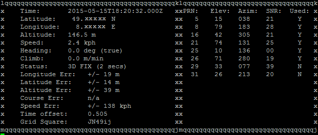
Make sure that the reception to the GPS satellites can be made, so go outside, or at least to a window. Where the reception in the house tends to be good, you can test with your phone.
19 Comments
Hello! Thanks for the guide! How would I send data collected from this sensor to the Azure IoT Hub?
Hmmm…. any GPS spits out Lat-Lon coordinates. How are you going to navigate with these???
In other words,connecting a GPs is TOTALLY USELESS without a navigation software. So. Where is the navigation software?
Try Navit.
This post is not useless, rather it is very interesting and to the point.
You should not criticize posts like this one if you are not able to fully understand them.
I’m interested in this project but I have not understood some things .
What does “Release serial interface” mean? What are we trying to do? And why?
What does “Storing is done with STR+O” mean?
I’m confused about the baud rate change. One paragraph says that we need to change it whereas the next suggests that we don’t.
What does “(CTRL + A, Q you finish)” mean?
Then: “we need to specify the baud rate…” but I don’t see it.
Is it me or do you need someone to check things to make them more understandable by the masses?
Write the instructions in American dialect please. Don’t assume everyone knows what you mean when you talk programming script.
Actually the above is in American dialect.
There is no “programming script”. The author is walking through the simple steps of editing a couple of files and installing software. Then running the command(s).
Maybe you should understand the environment more before criticizing.
I found quite a bit in the article to be odd, too.
The problem seems to be that the author assumes the user is in the ‘raspbian’ environment, and using ‘nano’ as the text editor. It would appear that only ‘raspbian’ still uses the ‘inittab’ environment, which was depricated by most of the other Linux distros years ago. ‘Releasing’ the serial interface — your guess is as good as mine; perhaps raspbian locks it upon boot for some reason?
‘nano’ appears to be a modeless text editor of some sort; it appears to be influenced by the Microsoft editors.
So, true; this is a poorly-written article. Nothing is explained, and actions are expected to be followed by rote. I think the style speaks more to the writers’ educational system (which emphasizes ‘rote’ over ‘reasoning’ or understanding) than to anything else. Look elsewhere for GPS integration with your Pi. I’m sure it’s out there; I’m about to go looking for it, myself.
I know I am late to this group, but I just had to reply. The article for what it is is good, not great but good. The report is OK, but I find people who do not want to research. This lack of rigor is technically not your fault because we live in a time where people are inconvenienced by looking for the answers when they are not readily put out there. However, the article gave me the basis to do research and find out things for myself. For instance, in some Linux versions, the serial interface is not used, so the location is locked to save memory. This locking makes the mem location unused for serial data; you noticed I did not say USB because the USB is taken care of but not the UART type of serial interface. There are some language issues, but those are quickly taken care of by asking or looking things up on your own.
If you are using the adafruit gps breakout board and have it connected by usb to the pi, try ttyUSB0 instead of ttyAMA0.
First of all maybe you should go a look up what GPS is/means.
Global Positioning System, it tells you where you are in the world.
It’s not totally useless without navigation and the author has just shown you how to use the module to get that information.
GPS Navigation which is what you are talking about is a whole separate piece to the pie. Maybe you should understand what your talking about before you are critical of someone else work.
Kodos to the author, I have not tried these steps but thank you for this part of the puzzle in working towards GPS on raspberry pi. But I am going to try them with the Raspberry Pi Tracking Hat. Will let you know how it works out.
So would this be able to send the position to another Pi or handheld gps?
Hi, may I just ask, how could I get the values of lat and long from the “cgps -s”? Is there a .py code needed. I would be sending the data to a database, could you please help me how?
Hi I’ve got an issue where I get n/a for everything and no fix in status
Anyone know how to fix it ?
Good afternoon,
I’m encountering an issue with this because my Raspberry Pi does not have /etc/inittab. How do I get around this? I’m assuming it’s because the evil systemd has taken this over like everything else it touches. LOL. Either way, just point me in the right direction and I should be able to figure out the rest.
Thanks
Hi, I also encounter the same problem !!
I just tried to install Navit from apt-get with a USB GPS.
A serial model can’t possibly be any worse that trying to navigate all the problems inherent in the GPSD software elements, the IPv4 and IPv6 networking and my IPTables firewall. It’s a nightmare.
However, having finally gotten the USB GPS to be seen Navit loaded with the error:
error:navit:xinclude:Unable to include /usr/share/navit/maps/*.xml
Why? Because there is no /usr/share/navit/maps/*.xml. The directory is empty….
Is there anything besides Navit?
Hello ! Great tutorials
So my question is will rasberry pi give me locations even if I am away from the pi ?
. I mean if I make a security system which notifies me when my pi is lost I mean the similar system to a mobile’s find my device system
Hi
Can I use any other third party GPS GNNS antenna with RPI? Is there any restriction what the system can not support?
THX
George