
Many of the sensors originally developed for the Arduino do not offer a digital interface and can only be read out analog. The problem is that the Raspberry Pi with its GPIOs cannot read out any analog signals, which is why you need an analog-digital converter (ADC) like the MCP3008. This means that up to 8 analog inputs can be read out via the SPI bus on the Raspberry Pi.
In this article, there is an explanation and a Python class, with which the signals of all analog sensors and modules can be read out.
One possibility is, of course, to connect an Arduino to the Raspberry Pi, since it also has analog IO pins and can, therefore, read out those signals without ADC. How this works is described in detail in the linked tutorial. The disadvantage of this, however, is that on the one hand, you have another microcontroller and that it cannot be addressed via Python. Since Python is particularly suitable as an entry-level programming language, most tutorials on this page also use Python. An Arduino, however, is programmed with C ++.
Required Hardware Parts
In addition to the MCP3008 ADC, you should also have Jumper Cables and a Breadboard.
In addition, there are a large number of sensors or modules that can only be read in analog, e.g.:
- Joysticks
- Infrared Distance Sensors
- Pulse/Heart Rate Sensors
- Sound Sensors
- Humidity Sensors
- Photo Sensors
- Rotary Encoders
- MQ Gas Sensors
- and many more
For most of these modules, you will also find more detailed instructions and/or projects that use them on this website. If you follow this tutorial, however, you will be able to read out any other analog sensor/module.
Differences Between Analog and Digital
There are only two states for digital signals: ON/HIGH or OFF/LOW (1 or 0). If one assumes a maximum digital input voltage of 5V, any value between 0V and 0.4V would be recognized as a LOW level and a value between 2.4V and 5V as a HIGH level. All values in between are undefined. If you apply such a voltage, the signal would be randomly recognized as 0 or 1. However, since this is not consistent, a digital signal should never be in this grey area.
In contrast to digital signals, an analog signal can also take intermediate values, so it is not clearly defined. For example, percentage values are given (value ÷ applied voltage), which many analog sensors use.
To read this voltage on the Raspberry Pi, an analog-digital converter like the MCP3008 must be used. However, this does not specify values in volts, but a number between 0 and 1023, which corresponds to 10 bits (2 ^ 10). The voltage can be determined as follows:
(ADC Value ÷ 1023) * Voltage
If the analog sensor is operated with a voltage of 3.3V and a value of 789 has been read out, the applied voltage corresponds to 2.54 volts.
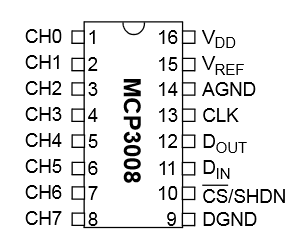
Connection Between Raspberry Pi and MCP3008
The easiest way to address an analog-digital converter is to use the SPI bus. All 8 signals can be read out with a query and converted.
As it can be seen in the datasheet, the ADC tolerates an input voltage between 2.7V and 5V. Since the GPIOs work with 3.3V and could break at higher voltages, the MCP3008 should only be operated with 3.3V. If you use an analog module that has a higher input voltage than 3.3V (and can also pass it on), you must make sure that it does not reach the ADC. For this, e.g. Series resistors are used and this may be taken into account in the further course (calculations, etc.).
The connection to the Raspberry Pi is quite simple since only those GPIOs are used that are also for the SPI bus:
| RaspberryPi | MCP3008 |
|---|---|
| Pin 1 (3.3V) | Pin 16 (VDD) |
| Pin 1 (3.3V) | Pin 15 (VREF) |
| Pin 6 (GND) | Pin 14 (AGND) |
| Pin 23 (SCLK) | Pin 13 (CLK) |
| Pin 21 (MISO) | Pin 12 (DOUT) |
| Pin 19 (MOSI) | Pin 11 (DIN) |
| Pin 24 (CE0) | Pin 10 (CS/SHDN) |
| Pin 6 (GND) | Pin 9 (DGND) |
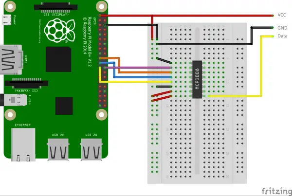
The connection then looks like this, although I have explicitly not placed a sensor on the right-hand side, as all digital signals can be read out in this way:
Preparation
Before the values can be read out, the packet sources must be updated and a library for SPI installed and of course, the SPI bus must be activated, as this is deactivated in Raspbian by default.
Let’s start by updating the packages and installing the Python Developer tools:
sudo apt-get update
sudo apt-get upgrade
sudo apt-get install python-dev
Then we can download, unpack and install the SpiDev library:
wget https://github.com/doceme/py-spidev/archive/master.zip
unzip master.zip
cd py-spidev-master
sudo python setup.py install
Last but not least, the SPI bus must still be activated if it has not already been done. In Raspbian Jessie (and other operating systems based on it), the configuration of the Raspberry Pi can be changed using sudo raspi-config. The “SPI” option can be found under “Advanced Options”. Here you activate SPI and then restart the system (if no corresponding query comes: sudo reboot).
Python Class for the Raspberry Pi ADC MCP3008
The following class allows you to easily access the MCP3008 ADC. You can either download the file here or create it using sudo nano MCP3008.py and insert the following code:
|
1 2 3 4 5 6 7 8 9 10 11 12 13 14 15 16 17 18 19 20 21 |
from spidev import SpiDev class MCP3008: def __init__(self, bus = 0, device = 0): self.bus, self.device = bus, device self.spi = SpiDev() self.open() self.spi.max_speed_hz = 1000000 # 1MHz def open(self): self.spi.open(self.bus, self.device) self.spi.max_speed_hz = 1000000 # 1MHz def read(self, channel = 0): adc = self.spi.xfer2([1, (8 + channel) << 4, 0]) data = ((adc[1] & 3) << 8) + adc[2] return data def close(self): self.spi.close() |
You can now insert this file into all of your project folders and simply integrate it:
|
1 |
from MCP3008 import MCP3008 |
The class must then be initialized once and the 8 analog channels can be read out:
|
3 4 5 |
adc = MCP3008() value = adc.read( channel = 0 ) # You can of course adapt the channel to be read out print("Applied voltage: %.2f" % (value / 1023.0 * 3.3) ) |
Now nothing should stand in the way of operating all possible Arduino/Genuino modules on the Raspberry Pi.
6 Comments
nice
Thanks! its works!
Would be nice if you explained what the xfer2 does
I am trying to connect a wind direction sensor to my MCP3008 which has ONLY 2 wires coming from it. One connects to the VCC, a resistor from pin 1 connects to ground and the other wire connects to pin 1 so I guess because of the resistor there are 3 connections per your above picture.
How ever all I can get for the value of the adc is 0.
The wind vane that I am trying to connect to the MCP3008 is made up of 8 reed switches and variable resistors so which ever switch is closed a different value is being sent to the MCP3008. When I try various Python programs that are supposed to read those values I get only 1 value regardless where the closed switch is located.
The tutorial I am following is from https://projects.raspberrypi.org/en/projects/build-your-own-weather-station.
Do you have any tutorials on this subject or know of any other reason why this is not working for me?
Thanks.
I got an error running the install of setup.py How do I get the setuptools library?
IIt is possible to connect two ADC modules?