
The advancement in the field of technology have also upgraded the orthodox methods of agriculture and replaced them with highly efficient and technically powerful tools. IoT (Internet of Things) is one of the most powerful things that allow us to control and monitor crops and plants over the internet. In this tutorial, we will learn how to make a smart agriculture system using ESP 32/NodeMCU. Our project will help us monitor the soil moisture of the plants or crops over the internet.
Requirements
You require the following things to make this project:
- Esp 32/Node MCU
- Soil Moisture Sensor
- Jumper Wires
- Water Level Sensor
- DHT11 Temperature and Humidity Sensor
- Relay Module
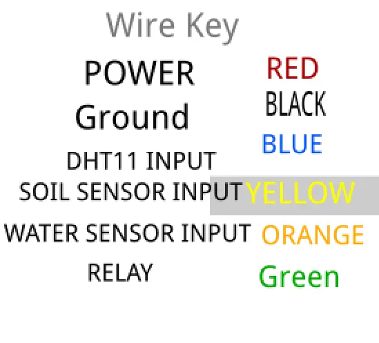
Circuit Diagram
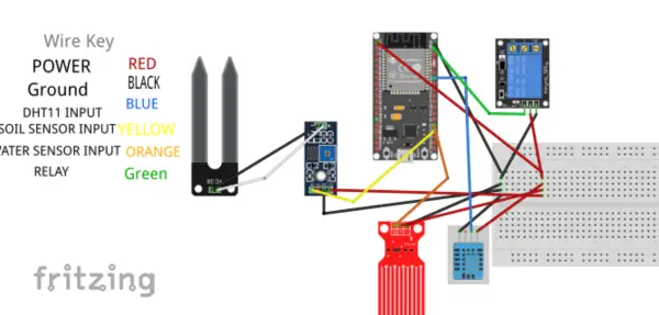
| Components | ESP32 Pins |
|---|---|
| DHT11 | GPIO 21 |
| Water Level Sensor | GPIO 2 |
| Moisture Sensor | GPIO 15 |
| Relay Module | GPIO 23 |
Working
ESP32/NodeMCU
Here, the NodeMCU/ESP32 is acting as the main microcontroller and its job is to fetch all the data from the soil, water, temperature and humidity sensors and send it over the internet to the Blynk app. Then this data is displayed on the Blynk app for the further monitoring. The output of the soil sensor and water sensor will be analog, so we have connected the analog pins of ESP32/NodeMCU with the soil sensor. The ADC (analog to digital converter) of our microcontroller will convert the analog signals from the sensor to digital signal. Then this signal will help us determine the need of water for our plants at appropriate times.
Soil Sensor
We are using FC-28 as the soil sensor.FC-28 Soil Moisture Sensor is an excellent tool for measuring moisture in soil and other materials like soil. It is very easy to use and understand. The two large pads are acting as a variable resistor. Since water is a conductor, so the quantity of water in between these pads decides the conductivity between them. The lower the resistance is, the higher the output we get, so we have high moisture in the soil.
DHT
The DHT11 is a cheap and a very accurate sensor for sensing both temperature and humidity. It consists of a thermistor and a capacitive sensing element. To measure the temperature DHT 11 has a negative temperature coefficient thermistor which decreases its resistance as the temperature increases that means higher the temperature is lower will be the resistance of that thermistor. It can measure temperature between a range of 0 to 50 degrees Celsius with accuracy up to 2 degrees. For humidity, the sensor uses a capacitor having two electrodes and holding a moisturized dielectric between them. The capacitance of this capacitor is sensitive to the moisture, so increase or decrease in moisture increases or decreases the capacitance. This change in moisture can be measured from 20 to 80 percent with an accuracy of 5 percent.
Water Level Sensor
The water level sensor works on the same principle as the soil moisture sensor. It is made of exposed parallel conductors that act like a variable resistor. The resistance of this variable resistor varies according to the water level. This change in resistance helps us to measure the height of water.
Relay Module
The Relay Module is used to control the motor or lights. If the water level is reduced to the minimum value of the tank, we can switch a motor remotely on to fill the tank. On the other hand, if the temperature is reduced to its minimum requirement, we can switch the lighting on to increase the temperature to a fixed value.
Blynk App
Blynk is an IOT platform that allows remotely controlling electronic devices over the internet through its servers. We can use blynk to do a lot of things like displaying data of sensors, storing it or controlling different appliances through relays over a very long distance. It works with three things:
- Blynk App – It is the main interface that helps us to make different widgets like buttons, switch charts and gauges and associate them with different pins of our microcontroller.
- Blynk Server – Blynk Server is responsible for all the communication between our mobile phones and the microcontroller. It helps us to control our microcontroller through the internet.
- Blynk Libraries – Blynk libraries are written to make our coding work easier. These actually help us to send and process all the commands that are necessary for the work of our microcontroller. Different libraries are written for different microcontrollers.
Working of Code
The DHT11 sensor library is being used in our code for the convenience. It helps us to get temperature and humidity values. Water and soil moisture are analog readings that can be mapper into a particular range. We are using two separate functions to send data to the Blynk App.
First function is used to send data of temperature and humidity.
|
1 2 3 4 5 6 7 8 9 10 11 12 13 14 |
void sendSensor1Data() { float h = dht.readHumidity(); float t = dht.readTemperature(); // or dht.readTemperature(true) for Fahrenheit if (isnan(h) || isnan(t)) { Serial.println("Failed to read from DHT sensor!"); //This function is used to take values of first two sensors return; } //Humidity and Temperature sensors value is taken through this function Blynk.virtualWrite(V5, h); Blynk.virtualWrite(V6, t); } |
Second function is used to send water and soil moisture levels.
|
1 2 3 4 5 6 7 8 9 10 11 |
void sendSensor2Data() { waterLevel = analogRead(waterLevelSensor); waterLevel = map(waterLevel,0,2000,0,20); moistureLevel = analogRead(moistureLevelSensor); moistureLevel = map(moistureLevel,0,4000,0,20); //This function is used to take value of Soil and Water sensor Blynk.virtualWrite(V7, waterLevel); Blynk.virtualWrite(V8, moistureLevel); } |
Virtual Write is a method of Blynk Library that helps us to read values from the virtual pins that we will configure when setting up our blynk app. Blynk timer object is used to send the values of temperature and humidity every two seconds and every five sends for water and soil moisture levels. Then these values are updated in the gauges of our app.
|
1 2 3 4 5 6 7 8 9 10 11 12 13 14 15 16 17 18 19 20 21 22 23 24 25 26 27 28 29 30 31 32 33 34 35 36 37 38 39 40 41 42 43 44 45 46 47 48 49 50 51 52 53 54 55 56 57 58 59 60 61 62 63 64 65 66 67 68 69 70 71 72 73 74 75 |
#define BLYNK_PRINT Serial #include <WiFi.h> #include <WiFiClient.h> #include <BlynkSimpleEsp32.h> //Different Libraries that are required for our smart agriculture systme #include <DHT.h> #include "DHT.h" #define DHTPIN 21 #define DHTTYPE DHT11 // DHT 11 const int waterLevelSensor = 2; const int moistureLevelSensor = 15; //Defining different required variables const int relay = 23; int waterLevel; int moistureLevel; DHT dht(DHTPIN, DHTTYPE); BlynkTimer timer; char auth[] = "YOUR AUTH CODE"; //authentication token sent from the blynk app // Your WiFi credentials. // Set password to "" for open networks. char ssid[] = "YOUR WIFI SSID"; //Enter your Wifi Credentials here char pass[] = "YOUR WIFI PASSWORD"; void sendSensor1Data() { float h = dht.readHumidity(); float t = dht.readTemperature(); // or dht.readTemperature(true) for Fahrenheit if (isnan(h) || isnan(t)) { Serial.println("Failed to read from DHT sensor!"); //This function is used to take values of first two sensors return; } //Humidity and Temperature sensors value is taken through this function Blynk.virtualWrite(V5, h); Blynk.virtualWrite(V6, t); } void sendSensor2Data() { waterLevel = analogRead(waterLevelSensor); waterLevel = map(waterLevel,0,2000,0,20); moistureLevel = analogRead(moistureLevelSensor); moistureLevel = map(moistureLevel,0,4000,0,20); //This function is used to take value of Soil and Water sensor Blynk.virtualWrite(V7, waterLevel); Blynk.virtualWrite(V8, moistureLevel); } void setup() { // put your setup code here, to run once: Serial.begin(9600); Blynk.begin(auth, ssid, pass); dht.begin(); // Setup a function to be called every second timer.setInterval(2000L, sendSensor1Data); //First function is called every 2 seconds timer.setInterval(5000L, sendSensor2Data); //Second function is called every 5 seconds } void loop() { // put your main code here, to run repeatedly: Blynk.run(); timer.run(); |
Setting up Blynk App
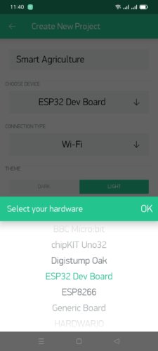
Step 1
Download Blynk from Play store (Blynk (legacy) – Apps on Google Play )or App Store (https://apps.apple.com/pk/app/blynk-0-1-legacy/id808760481). Then start a new project for your microcontroller.
Step 2
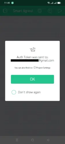
It will send you an authentication token to your email.
Step 3
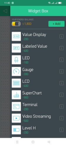
Add four Gauges for four respective sensors.
Step 4
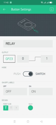
Also add a button to control the relay.
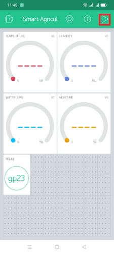
Step 5
You will have this screen. Start the project by tapping this button
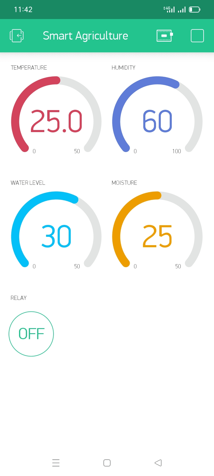
Step 6.
After you start the project, the values will display like this:
Summary
In this project, we have learned how to make a smart agriculture system that will help us to monitor different parameters that are necessary for the proper growth of the plants. This system is quite cheap as compared to the functionality. Every crop or plant have a specific temperature and water requirements, by using this project we can provide the best suitable conditions for the growing of a particular crop. We can further use the relay to control water motor and lights if temperature and water requirements are not met.
3 Comments
CAN I GET FULL REPORT FOR THIS PROJECT FOR MY RESEARCH
CAN I GET FULL REPORT FOR Steps & Code for Iot Based Smart Farming System using Raspberry Pi with python FOR MY RESEARCH
I also need this please!