
If you want to operate a weather station, you also have to think about the power supply. An autonomous supply of electricity by means of rechargeable batteries would be ideal. The ESP8266 solar panel power supply is of course an obvious solution. During the day, the microcontroller is supplied with electricity from the solar cell and a battery is charged at the same time. This energy storage device is then used at night.
In this tutorial, we look at how to connect the ESP8266 to the solar cell and what we need for the battery operation.
Required Hardware Parts
The ESP8266 can be powered with 5V via USB, as well as with 3.3V. In order to achieve a long battery life, we use 3.3V and corresponding batteries with a higher voltage. Then we throttle it. The solar panels should deliver at least 5V, 6V is better. I recommend that each solar module can deliver at least 500mA (better 750mA).
I have used the following components:
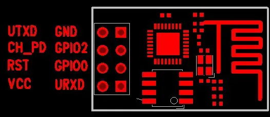
- NodeMCU Devboard or ESP-01
- 6V solar panel (you can also use several)
- Battery: Li-Ion type 18650B (with 3.7V) + a holder
- Battery charging module: Type TP4056
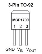
- 3.3V voltage regulator (MCP1700-3302E)
- Capacitors (100uF, but slightly different values are also possible)
- Cable + soldering utensils (or alligator clips)
As an alternative to the 3.7V Panasonic NCR18650B batteries, you can also connect normal 1.2V batteries in series, whereby these have less capacity (mAh). As an alternative or for testing, they can still be used (with a battery holder).
Setup and Connection of the Solar Panels on the ESP8266
In order to use solar panels with the ESP8266, we need a constant voltage of 3.3V. Here we could just use a linear voltage regulator between the solar cell and the ESP. However, this has the disadvantage that the power connection breaks off as soon as the sun is no longer shining.
For this reason, a battery must be interposed. If the solar panel generates enough electricity, the ESP should be supplied from it and the battery should be charged at the same time. During the night, the battery should then transfer its energy to the ESP8266. This ensures a constant power supply. There are special charging modules for this, such as the TP4056, which take on this task.
The charging module has a total of three slots (each with a plus and minus pole). First, we connect the solar cell to + and – (next to the USB port). If you use several solar cells, you can connect them in parallel (all plus poles to +, all minus poles to -). The battery or the battery holder is connected to B + and B– (plus to plus, minus to minus). Here, too, you can connect several batteries in parallel so that longer dark phases can be better survived without the power going out. This is particularly useful in winter
The OUT +/OUT connection remains. We connect the ESP8266 to this, but before that, we need the voltage regulator so that a constant 3.3V is output. This has 3 connections (VIN, VOUT, GND) and we connect it according to the following (diagram). The capacitor (shorter pin on GND):
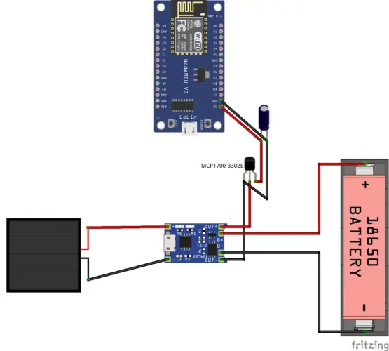
With the electrolytic capacitor (100uF) it is important that the longer side (+) is connected to VOUT and the shorter side to GND. You can now measure with the multimeter. The voltage should be constant at 3.3V, even if the solar cells are covered.
Last but not least, we connect VOUT and GND to the ESP-01/NodeMCU (here we take the 3.3V pin and GND.
Measure Solar Cell and Battery Voltage with the ESP8266
Depending on the weather and time of year, the battery is charged more or less well. So that the voltage does not drop too much, it makes sense to know the battery level and, if necessary, to reduce the power or even to put the ESP into standby mode.
The ESPs with more pins often also have an analog pin with which we can measure voltages up to 3.3V. The problem, however, is that the Li-Ion battery can output up to 3.7V (some sources even speak of up to 4.2V). This voltage can damage the ESP, so we need to get the voltage lower. To do this, we use a voltage divider that we can easily build ourselves with two resistors:
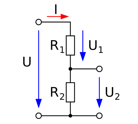
We know here that the maximum voltage is U = 3.7V and we want to achieve an output voltage U2 = 3.3V. According to the equation, this works as follows:
U2 = (U * R2) / (R1 + R2)
So we can freely choose the two resistors R1 and R2. Here you can either calculate your own values or take R1 = 12k Ω, R2 = 100k Ω.
3.3V = (3.7V * 100kΩ) / (12kΩ + 100kΩ)
If the maximum voltage of your battery is more or less than 3.7V, you have to adjust the values accordingly.
Now we connect the analog ESP pin between the two resistors, where R1 is connected to VOUT of the MCP1700-3302E and the other end of R2 is connected to GND.
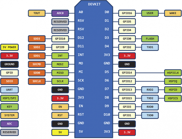
Then we can query the analog voltage value on the ESP32/NodeMCU Development Board. This works with the analog pin 10/ADC0 (see pin diagram above). With the ESP32 it is GPIO 33.
analogRead(0);
The value is a 12-bit value (0 to 4095) and indicates the level. So to find the voltage we have to divide by 4095 and multiply by 3.3.
Save Electricity with Deepsleep
If the ESP8266 is only supplied with power by a solar panel, it is all the more important that the consumption is not too high. Of course, it depends on various factors. You should place the solar cells in places with the longest and highest possible exposure to light. In addition, computationally intensive tasks on the ESP8266 are not recommended.
So in order to be as economical as possible, there are a few options:
- Deepsleep: The simplest method is to “let the ESP sleep” if it does not have to calculate anything. However, the Wi-Fi connection is also disconnected and the ESP cannot be addressed from the outside during this time. It is particularly suitable when values are to be recorded continuously (e.g. every 30 minutes) and sent to a server.
- Outsource calculations: Not all calculations have to take place on the ESP/NodeMCU. If possible, you can have computationally intensive actions carried out by others, such as a Raspberry Pi. A good example of this is facial recognition or machine learning algorithms.
- Go to sleep when the battery is low: If the power of the ESP is required, we can also measure the battery level in an interval and only activate deep sleep when the value falls below a certain level. We can only be active in solar radiation and reduce the measurements/functions at night.
- Use other wireless protocols: The connection to a Wi-Fi network needs up to 200mA, which is why there are better alternatives in solar operations. Via protocols such as Zigbee, values can be sent to the main station even without a Wi-Fi connection.
You are welcome to comment on other ways to save electricity with ESP8266 solar operation.
1 Comment
Portugal is a shining example of solar energy success! With its abundant sunshine, investing in solar panels not only cuts electricity bills but also supports a greener future. The country’s commitment to renewable energy makes it a fantastic place to harness solar power and reduce your carbon footprint.