
In the field of Raspberry Pi soil moisture measurement, there are resistive and capacitive sensors, which each have advantages and disadvantages. The innovative Raspberry Pi casting machine / DFROBOT Gravity or “Giess-o-Mat” sensor provides a permanently accurate capacitive measurement, which a.o. in our Raspberry Pi greenhouse can be very interesting.
This tutorial is about the structure of the Raspberry Pi casting machine as well as the reading of the frequency, with the help of which the relative soil moisture can be calculated.
Since I have been asked by several users and there is not much material on the subject (in terms of the Raspberry Pi), I hope that this tutorial will make using it a bit easier.
Required Hardware Parts
For this I have taken the following hardware parts or components:
- Raspberry Pi 4
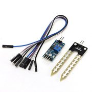
- Capacitive DFROBOT Gravity or “Giess-o-Mat” moisture sensor
- optional: frequency divider
- alternatively: multiple 100kΩ resistors
- Jumper Cable
- Soldering iron + solder
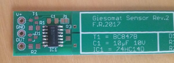
I recommend to take the coated version of the board right away, otherwise, it will anyway have to be manually sealed by hand. The supplied components of the board/sensor (listed below) are in SMD format and therefore not really suitable for beginners. With a little skill, the size should not be a problem.
The frequency divider can also be replaced by a resistor. In this case, the 100kΩ resistor at position R3 (see below) is replaced by a larger one: If the frequency is halved, a twice as large resistance is taken, etc. It is, of course, possible to combine several resistors.
Advantages over Resisitive Moisture Sensors
In a previous tutorial, we connected and read out a very low-priced soil moisture sensors on the Raspberry Pi. However, this design has a problem that occurs over time: corrosion. After prolonged use with the same polarity, the sensors often partially decompose. This is not good for the measuring behaviour nor for the soil values.
This danger does not exist with capacitive sensors. In this case, however, no analog signal is output, which can be read with an MCP3008 ADC, but a frequency that varies in height – depending on the humidity of the earth (the wetter, the lower).
The output frequency (up to 450kHz) is too much for the Raspberry Pi, which is why we either use a frequency divider that divides it by a certain dividend, or simply a bigger resistor. The disadvantage of a frequency divider is the price because a simple resistor costs almost nothing.
Assembly of the Raspberry Pi casting machine
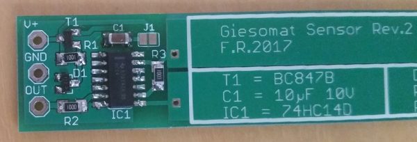
The Giess-o-Mat usually does not come assembled, which is why the individual SMD components have yet to be soldered onto the board. Since these are very small, a look on the label helps. I also tried to document each step with pictures, so nothing goes wrong.
The DFROBOT Gravity sensor is easier to handle: There is no soldering required, so you can ignore this step.
The following help sheet can be found in the bag of the components:
| Description | Type | Label | Function |
|---|---|---|---|
| T1 | BC847B | 1Ft od. 1FW | Transistor |
| C1 | 10μF 10V | Condenser | |
| IC1 | 74HC14D | HC14 | IC |
| D1 | BZX84B5V6 | T12 or Z3 | Zener diode 5v6 |
| R1 | 1k | 102 od. 1001 | Resistor 1k |
| R2 | 100R | 101 od. 1000 | Resistor 100R |
| R3 | 100k | 104 od. 1003 | Resistor 100k |
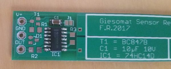
Let’s start with the IC. It is important that the side with the “up” mark shows where the little round notch can be seen on the PCB.
The capacitor (C1) has no label and it does not matter which side is soldered where:
With the resistors (R1, R2, R3) you must be careful since the SMD inscription does not correspond to the actual size. On this page, you can simply enter the imaged value of the SMD resistor and get the real size calculated.
If you do not have a frequency divider, you can also use a larger resistor instead of R3 (as described above).
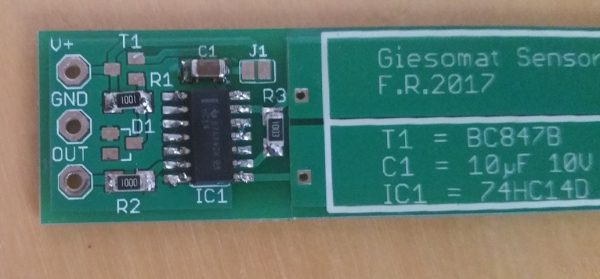
Subsequently, the only transistor (T1) and Zener diode (D1), which have the same shape, are missing. Here again, helps the label from above:
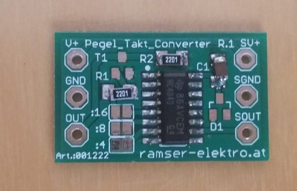
Assemble Frequency Divider (optional)
In the same way as the casting machine, we also build the frequency divider if we have one.
First the table:
| Description | Type | Label | Function |
|---|---|---|---|
| T1 | BC847B | 1Ft, 1F-, 1FW | Transistor |
| C1 | 10μF 10V | Condenser | |
| IC1 | 74HC4040 | HC4040 | IC |
| D1 | BAS40 | 43t, 43-, 43p, 43W | Schottky Diode |
| R1, R2 | 2k2 | 222, 2201 | Resistor 2k2 |
Again, we start with the IC, the capacitor and the resistors. The size of R1 and R2 is identical.
Still missing transistor (T1) and the diode (D1). Pay attention again to the label, as the design is identical:
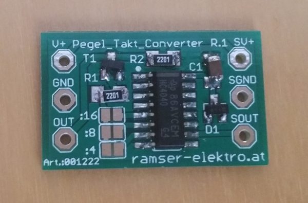
Last but not least, the two contacts of “: 16” are soldered together, resulting in a 16 times lower frequency.
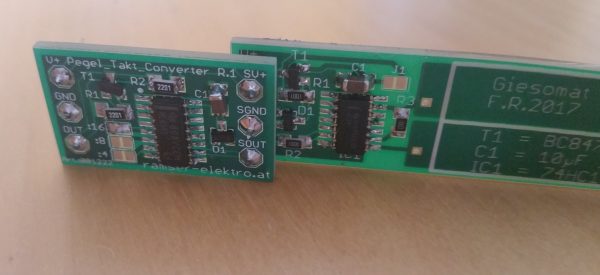
In addition, I have soldered the two boards together and soldered to the frequency divider a few contacts for the jumper cable.
A Script for reading the Frequency
First connect V + and 3.3V from the Raspberry Pi, GND to GND and OUT e.g. at GPIO21.
To read the frequency on Raspberry Pi is the PiGPIO library, which brings libraries for C (++), Python, etc. It is already preinstalled on ordinary Raspbian versions (not Lite), otherwise we can install it afterwards:
sudo apt-get update
sudo apt-get install pigpio python-pigpio python3-pigpio
Then we create a new C-file, which is there to read the frequency:
sudo nano freq_count_1.c
This file gets the following content (example from here). Save with CTRL + O and return CTRL + X to the terminal.
|
1 2 3 4 5 6 7 8 9 10 11 12 13 14 15 16 17 18 19 20 21 22 23 24 25 26 27 28 29 30 31 32 33 34 35 36 37 38 39 40 41 42 43 44 45 46 47 48 49 50 51 52 53 54 55 56 57 58 59 60 61 62 63 64 65 66 67 68 69 70 71 72 73 74 75 76 77 78 79 80 81 82 83 84 85 86 87 88 89 90 91 92 93 94 95 96 97 98 99 100 101 102 103 104 105 106 107 108 109 110 111 112 113 114 115 116 117 118 119 120 121 122 123 124 125 126 127 128 129 130 131 132 133 134 135 136 137 138 139 140 141 142 143 144 145 146 147 148 149 150 151 152 153 154 155 156 157 158 159 160 161 162 163 164 165 166 167 168 169 170 171 172 173 174 175 176 177 178 179 180 181 182 183 184 185 186 187 188 189 190 191 192 193 194 195 196 197 198 199 200 201 202 203 204 205 206 207 208 209 210 211 212 213 214 215 216 217 218 219 220 221 222 223 224 225 226 227 228 229 230 231 232 233 234 235 236 237 238 239 |
#include <stdio.h> #include <stdlib.h> #include <stdarg.h> #include <unistd.h> #include <pigpio.h> /* 2014-08-20 gcc -o freq_count_1 freq_count_1.c -lpigpio -lpthread $ sudo ./freq_count_1 4 7 8 This program uses the gpioSetAlertFunc function to request a callback (the same one) for each gpio to be monitored. EXAMPLES Monitor gpio 4 (default settings) sudo ./freq_count_1 4 Monitor gpios 4 and 8 (default settings) sudo ./freq_count_1 4 8 Monitor gpios 4 and 8, sample rate 2 microseconds sudo ./freq_count_1 4 8 -s2 Monitor gpios 7 and 8, sample rate 4 microseconds, report every second sudo ./freq_count_1 7 8 -s4 -r10 Monitor gpios 4,7, 8, 9, 10, 23 24, report five times a second sudo ./freq_count_1 4 7 8 9 10 23 24 -r2 Monitor gpios 4, 7, 8, and 9, report once a second, sample rate 1us, generate 2us edges (4us square wave, 250000 highs per second). sudo ./freq_count_1 4 7 8 9 -r 10 -s 1 -p 2 */ #define MAX_GPIOS 32 #define OPT_P_MIN 1 #define OPT_P_MAX 1000 #define OPT_P_DEF 20 #define OPT_R_MIN 1 #define OPT_R_MAX 10 #define OPT_R_DEF 5 #define OPT_S_MIN 1 #define OPT_S_MAX 10 #define OPT_S_DEF 5 static volatile int g_pulse_count[MAX_GPIOS]; static volatile int g_reset_counts; static uint32_t g_mask; static int g_num_gpios; static int g_gpio[MAX_GPIOS]; static int g_opt_p = OPT_P_DEF; static int g_opt_r = OPT_R_DEF; static int g_opt_s = OPT_S_DEF; static int g_opt_t = 0; void usage() { fprintf (stderr, "\n" \ "Usage: sudo ./freq_count_1 gpio ... [OPTION] ...\n" \ " -p value, sets pulses every p micros, %d-%d, TESTING only\n" \ " -r value, sets refresh period in deciseconds, %d-%d, default %d\n" \ " -s value, sets sampling rate in micros, %d-%d, default %d\n" \ "\nEXAMPLE\n" \ "sudo ./freq_count_1 4 7 -r2 -s2\n" \ "Monitor gpios 4 and 7. Refresh every 0.2 seconds. Sample rate 2 micros.\n" \ "\n", OPT_P_MIN, OPT_P_MAX, OPT_R_MIN, OPT_R_MAX, OPT_R_DEF, OPT_S_MIN, OPT_S_MAX, OPT_S_DEF ); } void fatal(int show_usage, char *fmt, ...) { char buf[128]; va_list ap; va_start(ap, fmt); vsnprintf(buf, sizeof(buf), fmt, ap); va_end(ap); fprintf(stderr, "%s\n", buf); if (show_usage) usage(); fflush(stderr); exit(EXIT_FAILURE); } static int initOpts(int argc, char *argv[]) { int i, opt; while ((opt = getopt(argc, argv, "p:r:s:")) != -1) { i = -1; switch (opt) { case 'p': i = atoi(optarg); if ((i >= OPT_P_MIN) && (i <= OPT_P_MAX)) g_opt_p = i; else fatal(1, "invalid -p option (%d)", i); g_opt_t = 1; break; case 'r': i = atoi(optarg); if ((i >= OPT_R_MIN) && (i <= OPT_R_MAX)) g_opt_r = i; else fatal(1, "invalid -r option (%d)", i); break; case 's': i = atoi(optarg); if ((i >= OPT_S_MIN) && (i <= OPT_S_MAX)) g_opt_s = i; else fatal(1, "invalid -s option (%d)", i); break; default: /* '?' */ usage(); exit(-1); } } return optind; } void edges(int gpio, int level, uint32_t tick) { int g; if (g_reset_counts) { g_reset_counts = 0; for (g=0; g<MAX_GPIOS; g++) g_pulse_count[g] = 0; } /* only record low to high edges */ if (level == 1) g_pulse_count[gpio]++; } int main(int argc, char *argv[]) { int i, rest, g, wave_id, mode; gpioPulse_t pulse[2]; int count[MAX_GPIOS]; /* command line parameters */ rest = initOpts(argc, argv); /* get the gpios to monitor */ g_num_gpios = 0; for (i=rest; i<argc; i++) { g = atoi(argv[i]); if ((g>=0) && (g<32)) { g_gpio[g_num_gpios++] = g; g_mask |= (1<<g); } else fatal(1, "%d is not a valid g_gpio number\n", g); } if (!g_num_gpios) fatal(1, "At least one gpio must be specified"); printf("Monitoring gpios"); for (i=0; i<g_num_gpios; i++) printf(" %d", g_gpio[i]); printf("\nSample rate %d micros, refresh rate %d deciseconds\n", g_opt_s, g_opt_r); gpioCfgClock(g_opt_s, 1, 1); if (gpioInitialise()<0) return 1; gpioWaveClear(); pulse[0].gpioOn = g_mask; pulse[0].gpioOff = 0; pulse[0].usDelay = g_opt_p; pulse[1].gpioOn = 0; pulse[1].gpioOff = g_mask; pulse[1].usDelay = g_opt_p; gpioWaveAddGeneric(2, pulse); wave_id = gpioWaveCreate(); /* monitor g_gpio level changes */ for (i=0; i<g_num_gpios; i++) gpioSetAlertFunc(g_gpio[i], edges); mode = PI_INPUT; if (g_opt_t) { gpioWaveTxSend(wave_id, PI_WAVE_MODE_REPEAT); mode = PI_OUTPUT; } for (i=0; i<g_num_gpios; i++) gpioSetMode(g_gpio[i], mode); while (1) { for (i=0; i<g_num_gpios; i++) count[i] = g_pulse_count[g_gpio[i]]; g_reset_counts = 1; for (i=0; i<g_num_gpios; i++) { printf(" %d=%d", g_gpio[i], count[i]); } printf("\n"); gpioDelay(g_opt_r * 100000); } gpioTerminate(); } |
Then we compile the files:
gcc -Wall -pthread -o freq_count_1 freq_count_1.c -lpigpio -lrt
Now the program can already be called. Only the corresponding GPIO pin must be specified, to which “OUT” is connected (eg 21):
sudo ./freq_count_1 21
Then the number of the GPIO followed by the frequency (in Hz) will be displayed. As a test, you can put the sensor in a glass of water and watch the frequency decrease.
In a project like the Raspberry Pi greenhouse, it is now important to find out the optimal value. However, this depends on the soil, the irrigation and the plants and therefore can not be answered clearly. For me, full wetness (glass of water) gave a frequency of about 1000Hz, with total dryness (no conductive material) about 10kHz (with a frequency divider of 16).
If you use a Python script, you can also extend/shorten the upper C program and integrate it into your Python script.
Further information on Giess-o-Mat
Further information about the casting machine is available a.o. on the following pages, most of which are for use with Arduino and/or ESP8266 and less with the Raspberry Pi. Nevertheless, I think that it can be worth reading links for those interested:
- https://www.mikrocontroller.net/articles/Giess-o-mat
- https://github.com/Zentris/erdfeuchtemessung
- http://www.n8chteule.de/zentris-blog/category/erdfeuchtemessung/
- https://wwwvs.cs.hs-rm.de/vs-wiki/index.php/Internet_der_Dinge_WS2015/SmartPlant#Messmethode_2:_Kapazitiv
If you know another good source, you can post it as a comment so I can expand the list.