
Often you want to control modules with a higher voltage with the Raspberry Pi. For this purpose, relays can be used on the Raspberry Pi: The relay “switch” is utilized by means of a low-voltage pulse. Since the Pi only tolerates a maximum of 5V (the GPIOs even only 3.3V) without relays, there is the risk that the Pi could burn out. However, if you have two separate circuits this can not happen.
In this tutorial, I will show how to control a relay with the Raspberry Pi and what has to be considered.
Required Hardware Parts
- 5V relay module
- Female – Female jumper cable
- an external circuit (e.g., batteries) and an application (eg, motors)
The relays are available as 2, 4, 8 and even 16 modules, depending on what you need. To avoid wasting too many GPIOs on the Pi it pays off to purchase a GPIO port expander with more than 4 channels.
Setup
The structure is very simple since all pins are labelled. Left (GND) comes to pin 6 of the Pi (GND), the right pin (VCC) comes to 3V3 (pin 1) of the Pis. Depending on how many of the relays you want to control, you need to connect a corresponding number of GPIOs to the IN pins. It is recommended to set a small resistor between the Pi and the relay, but it is not absolutely necessary with 3V3.
If you set 5V instead of 3.3V to VCC, you should definitely put one resistor each (~ 1kΩ) between the GPIOs and the IN pins.
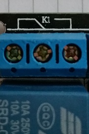
On the other side are at each relay 3 connections (see picture below): Depending on whether the IN pin is a LOW (0V) or HIGH (3.3V or 5V) is applied either the switch between the centre and right, or Open centre and left. If you connect all 3 pins, you can use the relay as a kind of switch, leaving it free on the left or right has the effect of an on/off switch. Where VCC or ground are connected (middle or right/left) does not matter.
If you want to connect devices with high voltages, you should either know exactly what you are doing or ask an electrician! 230V is life-threatening. Pay extra attention to the specifications of the relay and take, if possible, no dodgy parts from China (which doesn’t matter in the low-power range but at higher voltages you should spend a bit more and take proven products). I assume no liability for damages!
Raspberry Pi Relay Control
Also, the control is not very difficult, since only GPIOs have to be switched. You can use C++ (wiringPi) or Python for it. I am using Python and have used GPIO 17 (pin 11).
sudo python
|
1 2 3 4 5 6 7 |
import RPi.GPIO as GPIO GPIO.setmode(GPIO.BCM) # GPIO Numbers instead of board numbers RELAIS_1_GPIO = 17 GPIO.setup(RELAIS_1_GPIO, GPIO.OUT) # GPIO Assign mode GPIO.output(RELAIS_1_GPIO, GPIO.LOW) # out GPIO.output(RELAIS_1_GPIO, GPIO.HIGH) # on |
If 0V is present at the relay pin, the corresponding LED lights up, at a HIGH level the LED goes out. So if you want the relay to open at a HIGH level, you need to connect the middle and left pins to the circuit. The LED is off there. If the relay is to open, if the LED is also on, middle and right OUT pins are connected.
That’s it. I would like to know, in which applications have you found the use for the Raspberry Pi relays?
26 Comments
You can fry your Pi hooking your GPIO directly to your relays…
You need to put in a transistor and resistors in each connection.
And then you’ll fry the transistor and your GPIO.
You can drive the proper relay directly, but you need a snubber circuit to stop the inductive kickback caused by removing energy to the relay. You use a diode and a small capacitor for that.
hi Jacobus and Red!
I’ve had this doubt since I bought those relay boards. They do have a transistor and a diode and I think they are for protection. Isn’t that enought to protect the GPIOs?
The relay control boards almost all have a schottky diode placed in reverse and parallel to the relay to act as a flyback protection circuit. They are also made with an optocoupler (optoisolator) to electrically isolate the relay control circuit from the gpio pin. The optoisolator has control pins usually have a resistor in series with them somewhere to reduce the drain on whatever device is controlling it. However, since the relay boards operate at 5v, another resistor between the IN pin on the relay board and GPIO on the Pi is recommended. What I’m curious about is that the relays on most relay boards are 5v relays, meaning they require 5v in order to “switch on.” How can you provide only 3.3v from the pi to the relays and expect that to be enough to switch them them? Also, if you do use the Pi’s 5v as Vcc to the relay board, you probably shouldn’t put the Pi in a situation where the relay board may be “turning on” more than, say, 5 relays at once. If I recall, the coils in those 5v relays can draw around 30mA. The RPi 3 is only capable of supplying about 300mA safely from it’s +5v GPIO Vcc pin. Is it a good idea to drive relays from the Pi’s 5v pin?
The relay board shown in the photo above is the same as the one I have here on my bench, (about £5 from Amazon.co.uk) has an Opto isolator on each input to protect the GPIOs and a diode across each relay to protect the driver transistors on the board. You can also power the relays from a separate supply to protect the Pi’s power supply.
Yep. Its isolated optically. Shouldn’t need anything else to protect the Pi. Even the relays i’ve bought that are activated via transistor are fine because theyre just switching a transistor off n on to manage a higher current DC. (i do not power relays from the gpio header*) the higher current DC then throws the breaker by powering the coil. connecting the common to the NO normally open pin.
Not true…
These modules are complete.
Have current drivers, snubbers and are isolated.
Also have 5v or 3.3v logic levels selectable.
i love frying pi
I use Remote Desktop to control the RPi. I then start a program I wrote in Return To BASIC to control 16 Relays. One of the relays powers up my old Win XP driven Compaq which still will let me run 16 bit PowerBASIC compiled programs I wrote many years ago to work with my Weather Station.
I’m also using an old DOS program (created in VisualBasic for DOS). I’m now moving it to a Raspberry Pi with Linux and Dosbox-x because when the 20 year old PC will be dead, the program won’t run anymore. The program controls my central heating so you can imagine why I’m using the relays 😉
I don’t have a very technical background, can you elaborate on the arrangement of the transistor and resistor? Also what kind of transistor would be used?
Just put a 2kOhm resistor between Pi and relay board and you’ll be fine.
It’ll limit the drain to 2.5mA on that part of the circuit.
I am using single channel relay . After number of ON OFF switching the relay stops to respond to signal and don’t switch . is there a solution for such a problem
hello,
I am trying to use a control relay to operate for a certain duration of time. Could I use something like the import time feature and set the sleep.time(duration) as the on time and then turn off once the duration time is met?
Thanks in advance,
Yes, you could turn GPIO on, time.sleep(0.5), GPIO back off
Instead of `import RPi.GPIO as GPIO` you can write `from RPi import GPIO`
Hi
I came across this excellent tutorial whilst researching a means of one pi carrying out a soft reset on another. I spend time away from home and the pi looking after the tempratures for the heating sometimes stops. If I’m at home I can simply short “RUN” to an earth and away things go again. When I’m away I need a Pi Zero to do the “shorting” for me. I used to use, directly, a GPIO on the Pi Zero to do this but after some problems, I was looking at using a relay to close the “RUN to Ground” circuit; operating the relais by setting the GPIO pin from LOW to HIGH for a second and then back to LOW. Am I on the right track? Are there any earth continuity issues?
where having trouble as to how the relay will be triggered to switch. we have this thermal camera that aims to switch off the lights when no one is around and switches on when there is a person detected. how can we integrate the switching of relays by the command given by the thermal camera. thank youuu
Hello. Is it possible to control relays if we are using thermal camera to tell if when will the relay gonna turn off f or on? Send help. 😊
Hi
Am completely new to Raspberry Pi, Python and decided to dive in!
I found your article great and have managed to replicate this successfully in conjunction with an AM2302 to measure temp and humidity and switch relays on/off in response 🙂
However – I wanted to use a breadboard with its own 3.3/5v power supply to test multiple relays switching multiple circuits. It all seemed to go wrong once I went down this route as the relays stopped doing anything. After much head scratching it seemed that neither the AM2302 nor the relays would function using the power from the breadboard but only worked when connected back to the power out from the GPIO.
I tested the voltage on the breadboard and it’s def working – I have it set to 5v on one side of the board and 3.3v on the other and both are correct.
Does anyone have any idea what I’ve done wrong please? I was hoping not to power everything direct from the GPIO as that seems wrong!
Thanks 🙂
Did you connect power AND ground?
To use the board on the PI, it should be enough to remove the jumper and then power 5V from an external power source to the JD-VCC pin and connect the 3.3V reference from the PI to the VCC pin.
What is the best way to get the Raspberry Pi 4 to control 40-50 relays? SPI? UART? Shift register? Stacking boards?
What if I’m using the relay to switch a 12 V current, less than 5w total, do i still need to set up a protection ?
I have used the R Pi 3b+ and 8 channel relay board with a model railway 8 road n scale traverser which will take full length trains (about 6 ft long) . The RPi uses threading to control two NEMA 17 stepper motors with 3d printer screws to position the traverser. Each track has a dead section at the end to stop the train running off. As I need each relay to control 2 different voltages at the same time with 2 different earths and one is ac and one is dc I use each relay to operate another 2 pole double throw relay to switch the track on and off. It is all controlled from a 7 inch touch screen. When the traverser reaches the chosen track, the dead section is “livened” and the associated red led turns green. The 8 ch relay board is controlled with GPIO pins and the steppers with the SB Components motor shield. I have to clear the GPIO pins when the steppers stop and reset for the relay board and vv. Track selection is done with standard radio-buttons.
Sorry if this is a dumb question but what cable and connectors do you use to connect the Pi to the relay board? Do you have a link for those? Thanks