 on the Raspberry Pi")
Sooner or later, most hobbyists will buy a touchscreen. The smaller touchscreens are already available from 10-20€, but the advantages are big (especially with regards to a GUI for home automation, for example) and the effort is relatively low, as I’ll show.
As an example I will use a 3.2” SainSmart touchscreen, however, any other supported touch screen can be used as well.
Required Hardware Parts
- SainSmart 3.2” TFT LCD Display
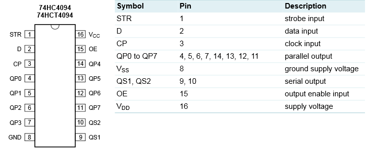
- 2x 74HC4094
- 1x 74HC04 (Hex Inverter)
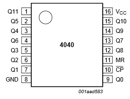
- 1x 74HC4040
- Jumper Cable
- Breadboard
If someone, like me, would like to solder the whole thing together and make an attachable shield on the TFT, needs a 2×20 socket strip, a breadboard and soldering tools.
Setup
Here are those pins that are directly connected to the Pi. They look like this:
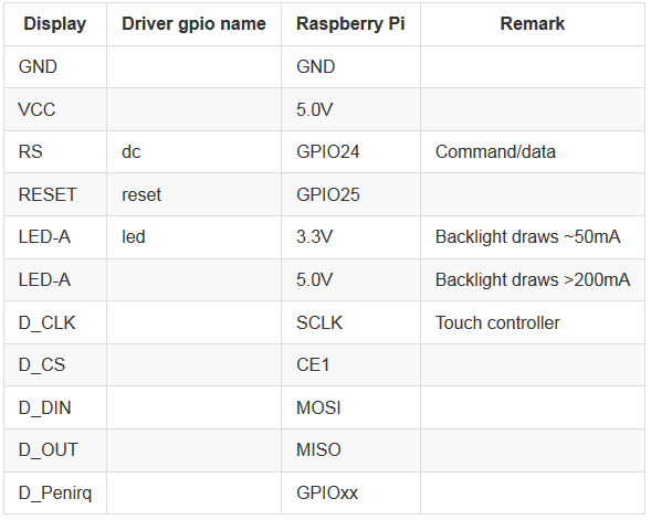
Here you can put D_Penirq on any free GPIO, you just have to specify this later. I took GPI23.
The other pins of the display must be connected via the blocks. Some pins of the Pi (like MOSI, SLCK, …) are used more often, this should be considered when connecting. The connections are as follows (on the left are the pins of the Pi, on the right those of the display).

The connections of GND components are not shown for clarity, but of course still have to be connected to the GND of the Pi.
In addition, the outputs are not all as shown on the right side, but distributed. Therefore, we look at the different components in detail:
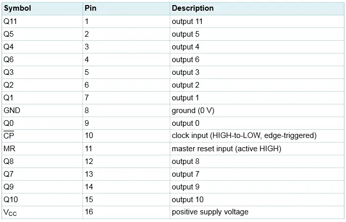
74HC4040 (Datasheet)
74HC4094 (Datasheet)
74HC04 (Datasheet)
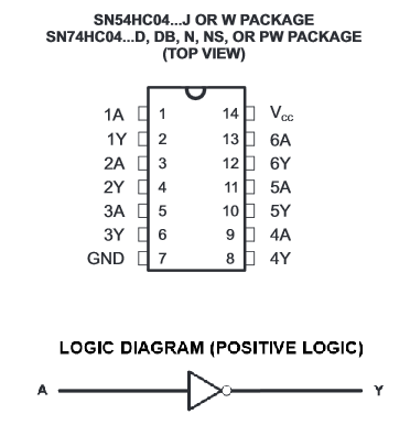
Dieses Bauteil hat mehrere Inverter. Wir benötigen nur eines davon. Zum Beispiel kannst du Pin 1 (1A) als Eingang nehmen (Ausgang von 74HC4040) und Pin 2 (1Y) als Ausgang zum Pin 5 (WR) des Displays.
Software
First of all, the system has to take the space of the whole SD card, if you have already done that, you can skip it. If not, go with it
sudo raspi-config
In the menu, you choose “Expand Filesystem” (first point) and confirm (also the question about the restart).
It must also be ensured that SPI is activated:
sudo nano /etc/modprobe.d/raspi-blacklist.conf
Comment out the corresponding line:
#blacklist spi-bcm2708
Now we load the drivers (which may take a few minutes) and restart:
sudo REPO_URI=https://github.com/notro/rpi-firmware BRANCH=latest rpi-update
sudo reboot
Afterwards
sudo modprobe fbtft_device name=flexfb rotate=1 speed=16000000 gpios=reset:25,dc:24and
sudo modprobe flexfb debug=3 width=240 height=320 regwidth=16 setaddrwin=2 init=-1,0x00,0x0001,-1,0x03,0xA8A4,-1,0x0C,0x0000,-1,0x0D,0x080C,-1,0x0E,0x2B00,-1,0x1E,0x00B7,-1,0x01,0x2B3F,-1,0x02,0x0600,-1,0x10,0x0000,-1,0x11,0x6068,-1,0x05,0x0000,-1,0x06,0x0000,-1,0x16,0xEF1C,-1,0x17,0x0003,-1,0x07,0x0233,-1,0x0B,0x0000,-1,0x0F,0x0000,-1,0x41,0x0000,-1,0x42,0x0000,-1,0x48,0x0000,-1,0x49,0x013F,-1,0x4A,0x0000,-1,0x4B,0x0000,-1,0x44,0xEF00,-1,0x45,0x0000,-1,0x46,0x013F,-1,0x30,0x0707,-1,0x31,0x0204,-1,0x32,0x0204,-1,0x33,0x0502,-1,0x34,0x0507,-1,0x35,0x0204,-1,0x36,0x0204,-1,0x37,0x0502,-1,0x3A,0x0302,-1,0x3B,0x0302,-1,0x23,0x0000,-1,0x24,0x0000,-1,0x25,0x8000,-1,0x4f,0x0000,-1,0x4e,0x0000,-1,0x22,-3
Your display should now turn black. To start the terminal or the desktop you have to enter the following:
Console
con2fbmap 1 1Desktop
FRAMEBUFFER=/dev/fb1 startx
So far so good. You’ll see that the touchscreen is not working yet. To do this, if necessary, stop the application with CTRL + C and enter:
sudo modprobe ads7846_device debug=1 cs=1 speed=2000000 model=7846 swap_xy=1 x_min=300 x_max=3800 y_min=700 y_max=3400 x_plate_ohms=60 pressure_max=255 gpio_pendown=23 keep_vref_on=1Where gpio_pendown=23 indicates the number of the GPIO (referred to above as GPIOxx).
If you are using the display in landscape mode, the touch will still be mirrored, so we need to install xinput:
sudo apt-get install xinput
Now we can start the desktop again:
FRAMEBUFFER=/dev/fb1 startx &
DISPLAY=:0 xinput --set-prop 'ADS7846 Touchscreen' 'Evdev Axis Inversion' 1 1
The second line “reflects” the touch axes again.
Autostart of the LCD Touchscreen Driver
To initialize the display (with touch) automatically at startup, 3 files have to be edited.
1. Let the modules load at startup.
sudo nano /etc/modules
At the end of the file are the following lines:
fbtft_device name=flexfb rotate=1 speed=16000000 gpios=reset:25,dc:24
flexfb debug=3 width=240 height=320 regwidth=16 setaddrwin=2 init=-1,0x00,0x0001,-1,0x03,0xA8A4,-1,0x0C,0x0000,-1,0x0D,0x080C,-1,0x0E,0x2B00,-1,0x1E,0x00B7,-1,0x01,0x2B3F,-1,0x02,0x0600,-1,0x10,0x0000,-1,0x11,0x6068,-1,0x05,0x0000,-1,0x06,0x0000,-1,0x16,0xEF1C,-1,0x17,0x0003,-1,0x07,0x0233,-1,0x0B,0x0000,-1,0x0F,0x0000,-1,0x41,0x0000,-1,0x42,0x0000,-1,0x48,0x0000,-1,0x49,0x013F,-1,0x4A,0x0000,-1,0x4B,0x0000,-1,0x44,0xEF00,-1,0x45,0x0000,-1,0x46,0x013F,-1,0x30,0x0707,-1,0x31,0x0204,-1,0x32,0x0204,-1,0x33,0x0502,-1,0x34,0x0507,-1,0x35,0x0204,-1,0x36,0x0204,-1,0x37,0x0502,-1,0x3A,0x0302,-1,0x3B,0x0302,-1,0x23,0x0000,-1,0x24,0x0000,-1,0x25,0x8000,-1,0x4f,0x0000,-1,0x4e,0x0000,-1,0x22,-3
ads7846_device swap_xy=1 debug=1 cs=1 speed=2000000 model=7846 x_min=230 x_max=3900 y_min=200 y_max=3700 x_plate_ohms=80 pressure_max=255 gpio_pendown=23 keep_vref_on=1
These are the same commands we previously used. So if you have other GPIOs and/or settings, you should adjust them. Save and exit with CTRL + O and CTRL + X.
2. Autologin
sudo nano /etc/inittab
You have to search for the top line (for example with CTRL + W) and comment out (with #). In the next line, you insert the described line.
#1:2345:respawn:/sbin/getty --noclear 38400 tty1
1:2345:respawn:/bin/login -f pi tty1 /dev/tty1 2>&1
3. X starting
sudo nano /etc/rc.local
After the comments, you add the following lines (again commands from above, if changed also change here). The sleep 3 ensures that X can fully charge before calibrating.
su -l pi -c "env FRAMEBUFFER=/dev/fb1 startx &"
sleep 3
su -l pi -c "DISPLAY=:0 xinput --set-prop 'ADS7846 Touchscreen' 'Evdev Axis Inversion' 1 1"
You can now reboot and will notice that the display should start immediately:
sudo reboot
In the second part, I will go into adjustments (like calibration).
If you have questions, you should take a look at the fbtft Wiki or post them in the comments.