
In addition to a surveillance camera and motion sensors, information about open windows and doors is also of interest to a self-built surveillance system. A check with infrared light barriers or other methods would certainly be possible, but in this case, that is much more complicated.
In this tutorial, it will be shown how to easily check the e.g. status of the window with a magnetic switch.
Required Hardware Parts
Luckily, not much is needed to attach the switch, and most parts are likely already present in most hobbyists crates. I have used these components:
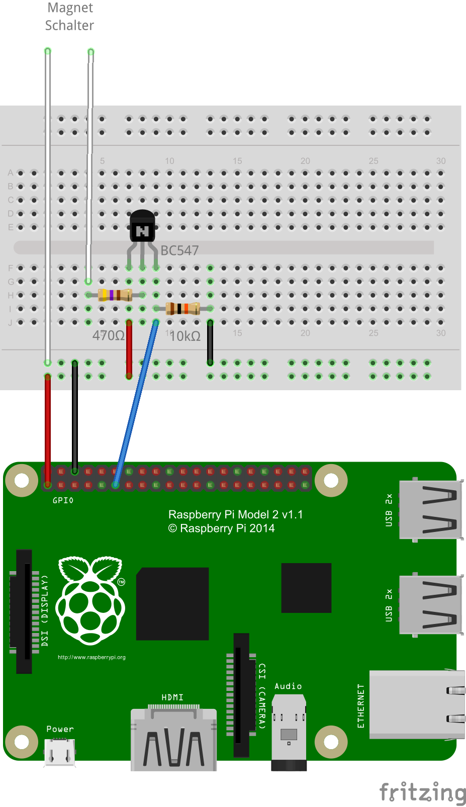
- 1 pair of magnetic switches
- Resistors (470Ω and 10kΩ)
- 1x BC547 Transistor
- Jumper Cable
Setup
The setup is as shown in the picture. As input pin I used GPIO 17 (board pin 11):

It does not matter which of the two cables of the magnetic switch is connected to the base of the transistor. The free end should be attached to the window/door and the one with cable best to the fixed door/window frame.
If the two parts are too far apart, it is possible that only a very small amount of electricity will flow through the transistor, which is insufficient to switch. In this case, you can try making a Pi’s connection 5V instead of 3.3V, but then you should definitely set a resistance between the transistor emitter and GPIO.
Of course, you could build this circuit as a pull-up resistor and thus would have a HIGH signal only when the window is open.
Controls
The controls are very simple and can be used in this form in many projects. Instead of my subsequent Python code, similar code can also be used e.g. in C ++ (using WiringPi).
But now to the code:
sudo python
|
1 2 3 4 5 6 7 |
import RPi.GPIO as GPIO GPIO.setmode(GPIO.BCM) # GPIO Numbers instead of board numbers MAGNET_GPIO = 17 GPIO.setup(MAGNET_GPIO, GPIO.IN) # GPIO Assign mode print GPIO.input(MAGNET_GPIO) |
As long as the window and thus also the magnetic switch is closed, a 1 is displayed on the pin. As soon as the contact is interrupted, the transistor no longer switches and a zero is displayed on the GPIO. This will allow you to query if a window/door is opened or not.
If you want to wait for the state to change, you can use the following function:
|
1 |
GPIO.add_event_detect(MAGNET_GPIO, GPIO.BOTH, callback=my_callback) |
In this case, a function called my_callback() must be present, which is then called. Here are the states GPIO.RISING and GPIO.FALLING instead of GPIO.BOTH possible.
8 Comments
This constantly has a drain of electricity why not test just a pin on the PI to see if it is HI if so alarm eliminate the transistor and one resistor.
Ralph
One thing I haven’t seen on construction of a PI security system is the question of cable length that run from the PI to the sensors. I understand the concept of voltage drop but not sure about anything other voltage out. Is there a recommendation of max cable length and if so is there a solution such as a repeater or a way to interface multiple PI units as one interface? Was thinking of maybe using something like Cat6.
I haven’t actually measured the voltage drop on the long wires that I’m using, but I have wires that run well over 50 feet and still work perfectly well with Raspberry Pi’s GPIO pins. I have several door sensors, as well as a water sensor, which is just two wires that short out when contacting water. For the door sensors I’m actually reusing the existing wiring from an ancient security system that came with the house. And for the water sensors I’m using cheap speaker wire. No issues so far.
Nice, thanks for sharing.
I’m about to give this a go as a test, but ran into a fundamental question on the planning board :): how do you scale this up to handle like 50 sensors? Obviously the goal would be to be able to individually identify the particular magnet failing, and there’s only so many GPIO pins available.
In theory, the best would be to join all the sensors and make them available via some bus, but that is beyond my understanding (today, lol)
Use a GPIO multiplexor chip or (since they are basically magnetic reed switches) you could utilize a Matrix style circuit and use an I2C Controlled Keypad Scan IC (like a TI TCA8418 https://www.ti.com/product/TCA8418). Each sensor would act like a button press on a keypad. A Matrix circuit is basically switches or LEDs wired into rows and columns (http://www.circuitstoday.com/wp-content/uploads/2017/08/4X4-Matrix-Keypad-Circuit-Connections.jpg). It would use one I2C interface and support up to 80 switches with the TCA8418.
I’ve wired everything exactly as shown, 3.3v, on a raspberry pi 4 model b, I keep seeming to kill the gpio pins and I cannot figure out why.
I’m now using GPIO23 / board 16 – it’s not being killed but I’m getting constant 0’s regardless of whether there is contact with the magnetic switch or not. If I disconnect the connection to GPIO23 1’s show, so it is the correct pin.
Hi
I have a question, sorry if it is dumb as I am a beginner but aren’t you floating the base of the transistor?
If the switch is closed then it is grouned, however if it is open then the base is floating? won’t this produce an unpredictable behavior?
Also why not just use the switch with a resistor? what is the significance of the transistor?
Thank you
I tried this is 3.3V in using a benchtop power supply and nothing connected to the emitter – it draws 1.5A???
I tried it with 5v and it draws 3A!!
What size resistor do you recommend when using 5V on the emitter. How come this circuit draws so much?