It continues with the second part and the actual Traffic Light Circuit. Let’s take a look at the various Traffic Light Signals on Wikipedia. We want to recreate them at the push of a Button.

(Source: Wikipedia)
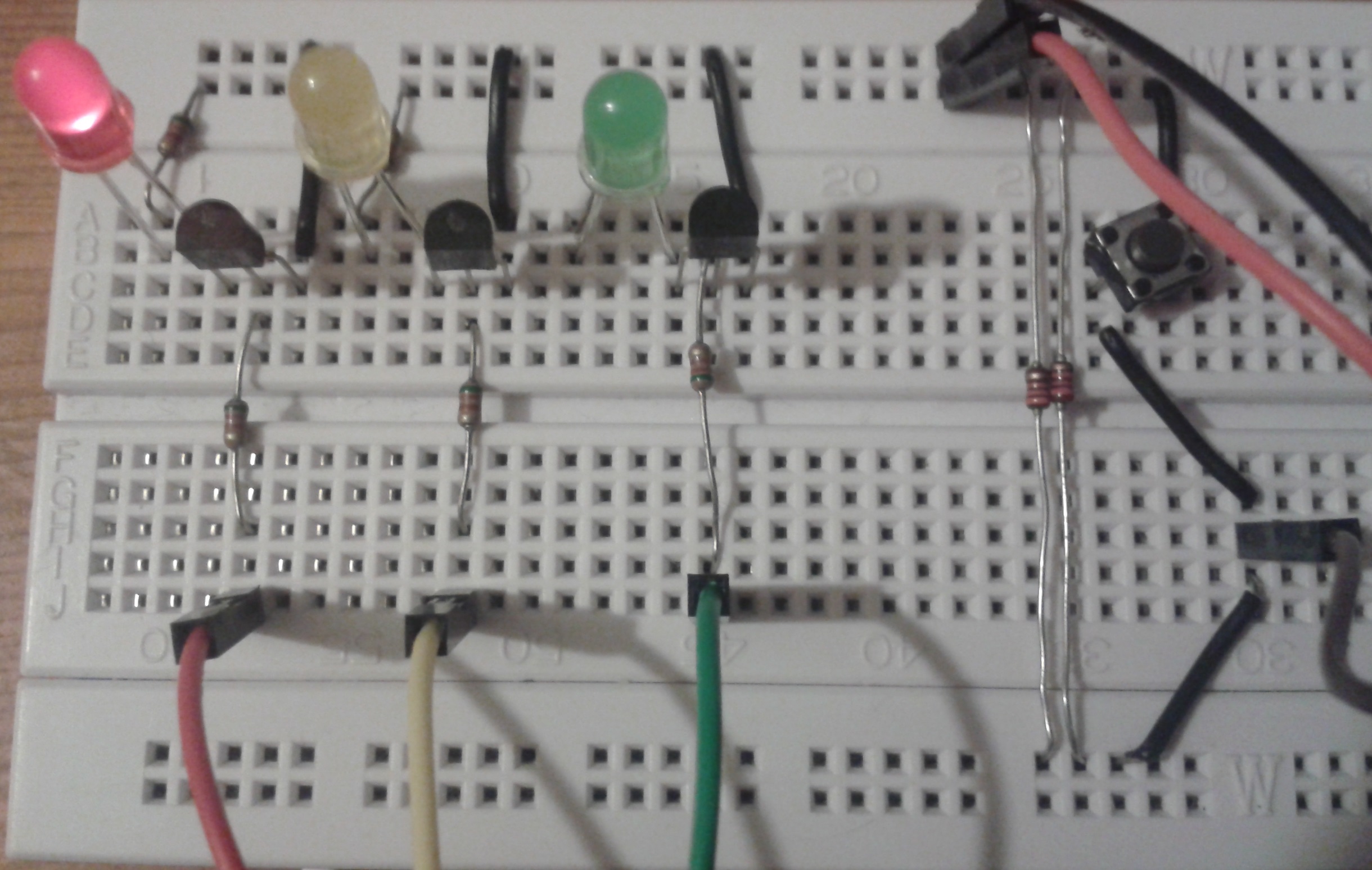
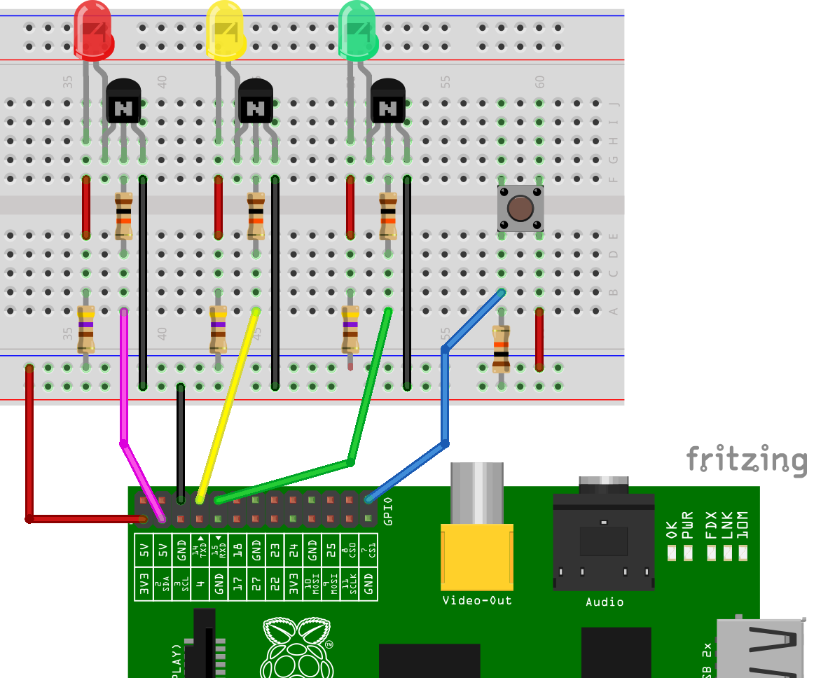
First of all, we build the Circuit:
So we have the following Phases:
- no Button pressed – permanently red (yellow and green off)
- Button is pressed – red and yellow light up (green off), duration: 3 seconds
- Change to green (red and yellow off), duration: 15 seconds
- Change to yellow (red and green off), duration: 3 seconds
- Back to Step 1.
This now has to be converted into Code. For example, I created a Script for this:
sudo nano ampel_skript2.py
This time, instead of the Pin Numbers, I use the GPIO Numbers.
|
1 2 3 4 5 6 7 8 9 10 11 12 13 14 15 16 17 18 19 20 21 22 23 24 25 26 27 28 29 30 31 32 33 34 35 36 37 38 39 40 41 42 43 44 45 46 47 48 49 50 51 52 53 |
#Bibliotheken einbinden import RPi.GPIO as GPIO import time #GPIO Modus (BOARD / BCM) GPIO.setmode(GPIO.BCM) #Warnungen ausschalten GPIO.setwarnings(False) #GPIO Pin Belegung ROT = 02 GELB = 14 GRUEN = 15 TASTER = 07 #Richtung der GPIO-Pins festlegen (IN / OUT) GPIO.setup(ROT, GPIO.OUT) #rot GPIO.setup(GELB, GPIO.OUT) #gelb GPIO.setup(GRUEN, GPIO.OUT) #gruen GPIO.setup(TASTER, GPIO.IN) #Taster #Umschaltung definieren def umschalten(): #Phase 2 GPIO.output(ROT, True) GPIO.output(GELB, True) GPIO.output(GRUEN, False) time.sleep(2) #Phase 3 GPIO.output(GRUEN, True) GPIO.output(ROT, False) GPIO.output(GELB, False) time.sleep(15) #Phase 4 GPIO.output(GELB, True) GPIO.output(GRUEN, False) time.sleep(3) #zurueck zu Phase 1 GPIO.output(ROT, True) GPIO.output(GELB, False) #Endlosschleife while True: #Phase 1 GPIO.output(ROT, True) GPIO.output(GELB, False) GPIO.output(GRUEN, False) #Status des Tasters einlesen tasterStatus = GPIO.input(TASTER) if (tasterStatus): umschalten() |
It is called again with
sudo python ampel_skript2.py
The red LED lights up and pressing the Button calls up the Function and changes the Traffic Lights. Execution of the Script terminated with CTRL + C.
The Functions can be changed and extended. Here is a Picture of my Circuit.