
For the Arduino and Raspberry Pi there are some keypad matrixes that can be connected and read relatively easily. Similar to the numpad on a keyboard, these keypads have 3×4 or 4×4 keys. These modules can be used, for example, as code locks or for the construction of a small pocket calculator. With help of a few small changes, even a T9 keyboard can be created, with which texts can be typed like on older mobile phones.
In this tutorial, I will show the connection of such a keypad matrix and how to easily read them with the GPIOs. In order to use fewer GPIOs, it is also possible to connect it via the I2C Port Expander MCP23017.
Required Hardware Parts
As I already mentioned, there are several different models of these “membrane switches”, which mainly differ in size and labelling. In this tutorial, I used a 3×4 keyboard, but there is no problem adjusting it for a 4×4 (or larger) keypad.
The following models are available:
- 3×4 Keypad Matrix
- 4×4 Keypad Matrix
- special variants of the 4×4 keypad with printed letters (T9 Style)
You should also have male-female jumper cables on hand.
It does not matter which Raspberry Pi model you use as long as you have at least 7 or 8 unused GPIOs.
Connection and Function of the Raspberry Pi Keypad
Basically all free and controllable GPIOs can be chosen for it. Depending on whether you have a 3×4 or 4×4 matrix membrane 7 or 8 pins will be occupied. Best suited for it are male-female jumper cables, which fit into the terminals of the keypad. The basic structure of such a keyboard matrix is as follows:
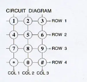
The first 4 pins from the left are here for the lines, the other 3 or 4 connections for one column. As soon as a key is pressed, two lines are connected. To find out and, if so, which key was pressed, a signal is sent in each case by the first four lines. The remaining pins are “tapped”.
If e.g. only key 6 was pressed, the lines “row 2” and “column 3” would be connected. So if we send a stream to the GPIO for line 2, only a high signal will be received at the GPIO for column 3. All other GPIOs receive no signal. So by sending a signal through all the rows and then checking all the columns, we can tell if a key was pressed and of course which one.
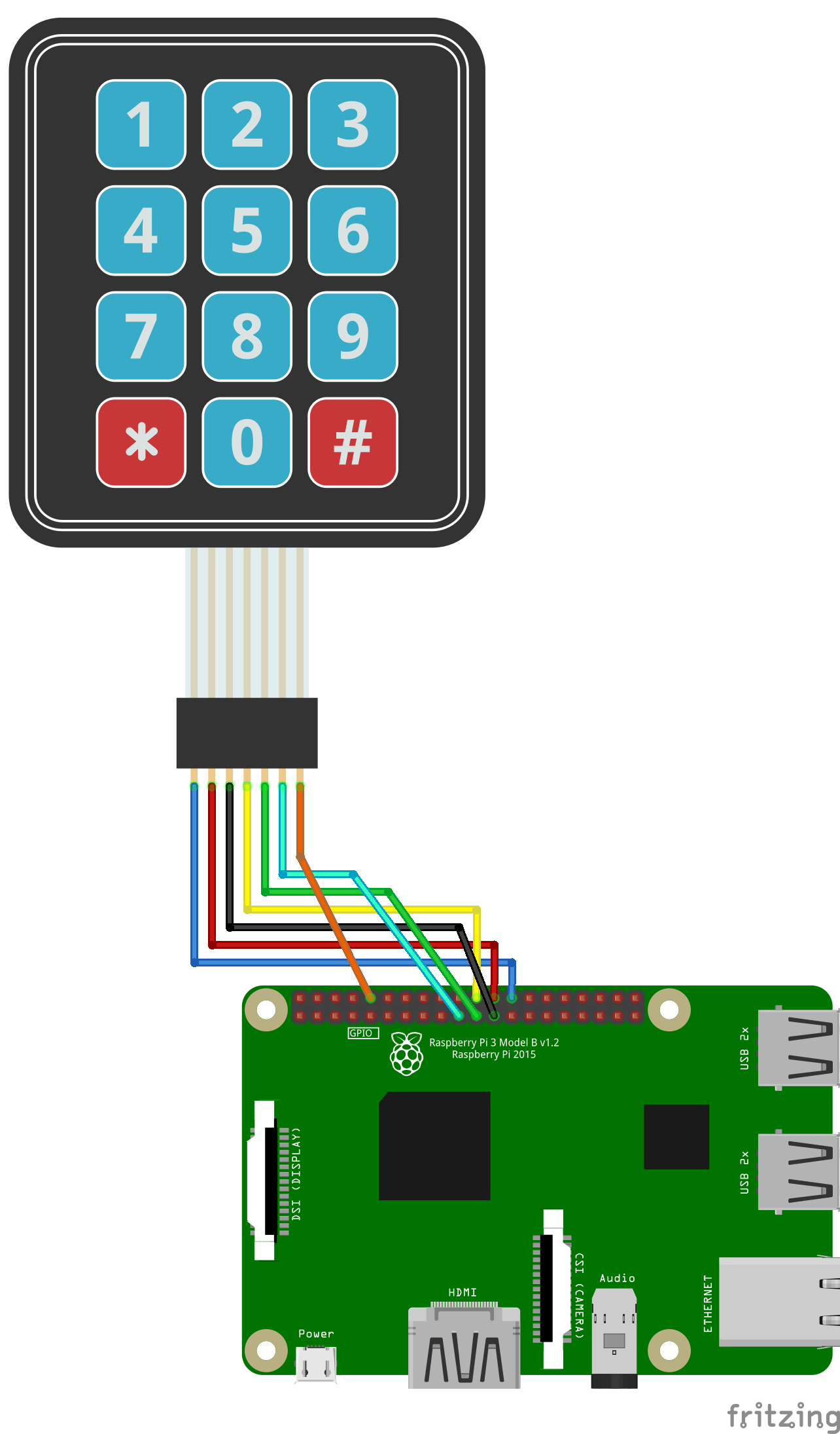
Well, as already mentioned, it does not matter which 7 or 8 GPIOs you use, but this must be adjusted later in the code if necessary. In this example, I use a 3×4 keypad, so I only have 7 GPIOs to allocate. From left to right the occupancy is as follows:
| 3×4 Keypad | Raspberry Pi |
|---|---|
| Pin 1 | GPIO 7 (Pin 26) |
| Pin 2 | GPIO 8 (Pin 24) |
| Pin 3 | GPIO 11 (Pin 23) |
| Pin 4 | GPIO 25 (Pin 22) |
| Pin 5 | GPIO 9 (Pin 21) |
| Pin 6 | GPIO 10 (Pin 19) |
| Pin 7 | GPIO 15 (Pin 10) |
Schematically it looks like this:
Code for steering the keypad
To be able to use the small keyboard now, we load ourselves a small library of GitHub. First we create a folder.
mkdir keypad-rpi && cd keypad-rpi
Then we download the file:
wget -O keypad.py https://raw.githubusercontent.com/rainierez/MatrixKeypad_Python/master/matrix_keypad/RPi_GPIO.py
If you are using a 4×4 keyboard or GPIOs different than me, you will need to adjust the GPIO numbers in the code accordingly (sudo nano keypad.py).
Now we can use that class. To clarify the functionality, I have created a small example. To copy this, create a new file
sudo nano example.py
with the following code:
|
1 2 3 4 5 6 7 8 9 10 11 12 13 14 15 16 17 18 19 20 21 22 23 24 25 26 27 28 29 30 31 |
import time import RPi.GPIO as GPIO from keypad import keypad GPIO.setwarnings(False) if __name__ == '__main__': # Initialize kp = keypad(columnCount = 3) # waiting for a keypress digit = None while digit == None: digit = kp.getKey() # Print result print digit time.sleep(0.5) ###### 4 Digit wait ###### seq = [] for i in range(4): digit = None while digit == None: digit = kp.getKey() seq.append(digit) time.sleep(0.4) # Check digit code print(seq) if seq == [1, 2, 3, '#']: print "Code accepted" |
You can save and quit the file with CTRL + O, CTRL + X.
If we execute the file now, the inputs can be selected.
sudo python example.py
In the following video you can see how the reading of the numbers can look like:
11 Comments
Hi, i am Federico, i have a raspberry pi 3B and when i compile the file with geany, it says to me:
<>
where and how can i install it?
How to connect a 4×4 keypad?
Anyone want to apply this to a 4×4 matrix keypad – you need to set the appropriate pin numbers in keypad.py (lines 24 & 25)
However, you also need to fix a bug in the code:
Simply change line 75 of keypad.py
from:
if colVal 2:
to:
if colVal len(self.COLUMN):
yeah i have a 4×4 to
digit = kp.getKey()
File “/home/pi/keypad.py”, line 43, in getKey
GPIO.setup(self.ROW[i], GPIO.IN, pull_up_down=GPIO.PUD_UP)
ValueError: The channel sent is invalid on a Raspberry Pi
Same error
Traceback (most recent call last):
File “example.py”, line 14, in
digit = kp.getKey()
File “/home/pi/keypad-rpi/keypad.py”, line 38, in getKey
GPIO.setup(self.COLUMN[j], GPIO.OUT)
ValueError: The channel sent is invalid on a Raspberry Pi
Try a different GPIO pin, or you may referencing a power pin. Look through our row and column pins and check the board pin numbers, not the BNC pin numbers
# if colVal is not 0 thru 2 then no button was pressed and we can exit
if colVal 2:
self.exit()
return
Is only correct if you have a 3×3, with this a 4×4 will never register the far right col.
Change to:
if colVal 3:
self.exit()
return
Error in the above code line 16: print digit should be print(digit). Similar error in keypad.py about line 100.
Line 20 is: seq = [] (square brackets not a box)
When running the code, the section ” #waiting for a keypress” traps the first key you press, then prints it.
The next section waits for four keypresses IN ADDITION to the one you just pressed.
If you try ‘1, 2, 3, #’ the first press gets trapped and the sequence never sees it.
Comment out the ‘waiting for keypress’ and the ‘print’ right after it to test out the ‘4 Digit wait’
i got the same error
Traceback (most recent call last):
File “keypadv3.py”, line 14, in
digit = keypad.getKey()
TypeError: unbound method getKey() must be called with keypad instance as first argument (got nothing instead)
I would like to set a pin high to turn on an led if the code is correct, I tried GPIO.setmode(GPIO.BCM) GPIO.setup(20, GPIO.OUT, initial=GPIO.LOW) and GPIO.output(20, True) but I am getting errors