
If you have several smaller or one larger project, you will soon discover that the GPIO pins of the Raspberry are fastly becoming too little. For all of you, this tutorial will show you how to use an I2C Port Expander to easily multiply the GPIO pins many times over.
In some situations, you may need more GPIO pins than it has outputs and you are at its physical limits. But there is a very useful port expander. On the use of one of these, we will discuss in this post.
Required Hardware Parts & General
For this tutorial you need the following hardware parts:
- MCP23017
- LEDs (best in different colors)
- a button
- Resistors
- Breadboard
- Jumper cable
First of all, the setup of the microchips:
As you can see the differences are minimal, for this tutorial it does not matter which one is used.
Preparation
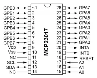
A little explanation of the main pins:
- GPA0-7 and GPB0-7 are the GPIO pins
- A0, A1, A2 are connected to + (3.3V) or – (GND) and define the name internally. If several port expanders are connected, each must be clearly identifiable. With the first I²C you would connect all to GND, the next A0 to 3.3V and the other two to GND. At the third a! at 3.3V and the other two at GND etc. So it is possible up to 2³ and to connect an 8 port expander.
- VDD (Pin 9) gets the input voltage (3.3V)
- VSS (pin 10) is connected to GND
- SCL (pin 12) is connected to the GPIO pin 5 of the Pi
- SDA (pin 13) is connected to the GPIO pin 3 of the Pi
Accordingly, I have built a small circuit with 3 LEDs (as series resistors 330Ω).
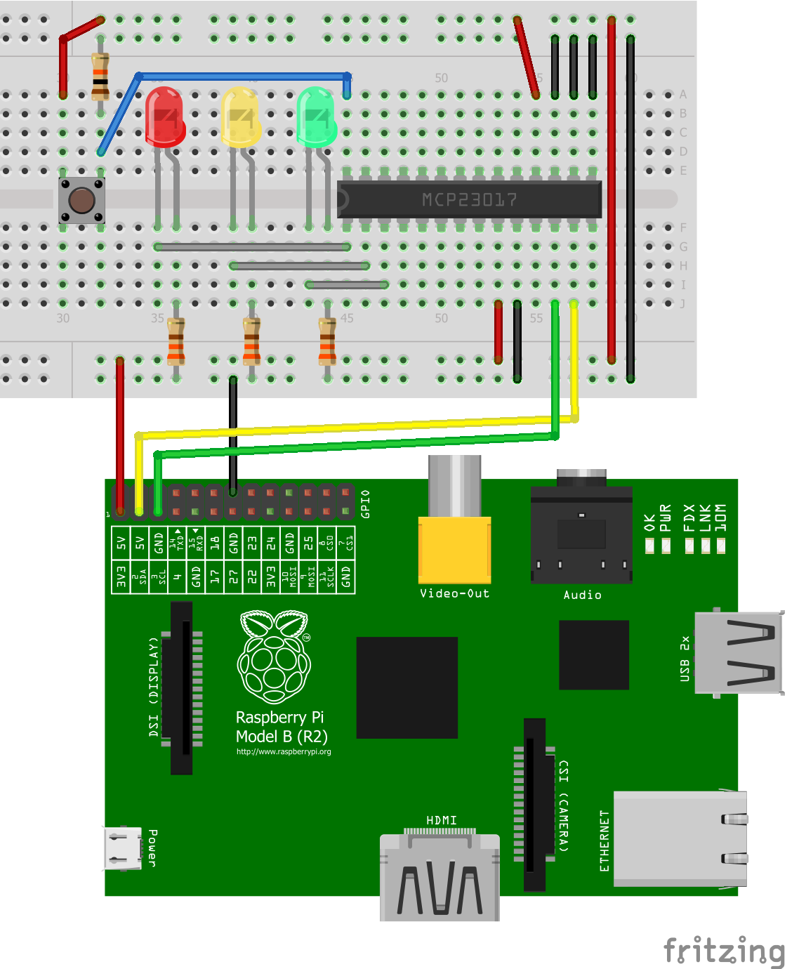
(We require the button only in Part 2 of the tutorial.)
The first thing to do is to unlock the I2C in the Pi. The easiest way to do this is by means of
sudo raspi-config
It is activated under “Advanced Options”> “I2C”.
For older versions of Raspbian, you also have to edit a file
sudo nano /etc/modules
and appends these two lines to the end:
i2c-bcm2708
i2c-dev
Save and exit with CTRL + O and CTRL + X.
Now the modules have to be removed from the blacklist file, otherwise, they will not work.
sudo nano /etc/modprobe.d/raspi-blacklist.conf
and put a # in front of the two entries.
#blacklist spi-bcm2708
#blacklist i2c-bcm2708
Save again with CTRL + O and CTRL + X and exit.
So that we can address the I2C now, we have to install a few more packages.
sudo apt-get install python-smbus i2c-tools
Then shut down the Pi, wait a few seconds and disconnect from the power.
sudo shutdown now
Testing Hardware
After everything is connected and all connections have been checked again, start the Pi and wait until it has started up.
I use a Raspberry Pi Rev.2, so I test it with:
sudo i2cdetect -y 1
If you have a Pi Rev.1, you must enter 0 instead of 1. The output looks like this:
pi@raspberrypi ~ $ sudo i2cdetect -y 1
     0  1  2  3  4  5  6  7  8  9  a  b  c  d  e  f
00:          -- -- -- -- -- -- -- -- -- -- -- -- --
10: -- -- -- -- -- -- -- -- -- -- -- -- -- -- -- --
20: 20 -- -- -- -- -- -- -- -- -- -- -- -- -- -- --
30: -- -- -- -- -- -- -- -- -- -- -- -- -- -- -- --
40: -- -- -- -- -- -- -- -- -- -- -- -- -- -- -- --
50: -- -- -- -- -- -- -- -- -- -- -- -- -- -- -- --
60: -- -- -- -- -- -- -- -- -- -- -- -- -- -- -- --
70: -- -- -- -- -- -- -- --
The address 0x20 (hexadecimal) contains the I2C. If A2 were e.g. connected to 3.3V (A1 and A0 to GND), it would be addressable at the address 0x24. This is, as mentioned above, important if you have connected several port expanders in order to be able to address them clearly.
To address the LEDs, the ports must either be declared as input or output (Rev1 please adjust the user again).
sudo i2cset -y 1 0x20 0x01 0x00
Here are some examples that explain how the command works:
i2cset -y 1 0x20 0x01 0x00   #all pins of GPB are output
i2cset -y 1 0x20 0x01 0x04   #GPB2 is input, the rest of GPB output (since 0x04 in binary 00000100)
i2cset -y 1 0x20 0x00 0x80   #GPA7 is input, the rest of GPA output
First of all the address addressed by i2cdetect is addressed. The second value is in this table (from the datasheet):
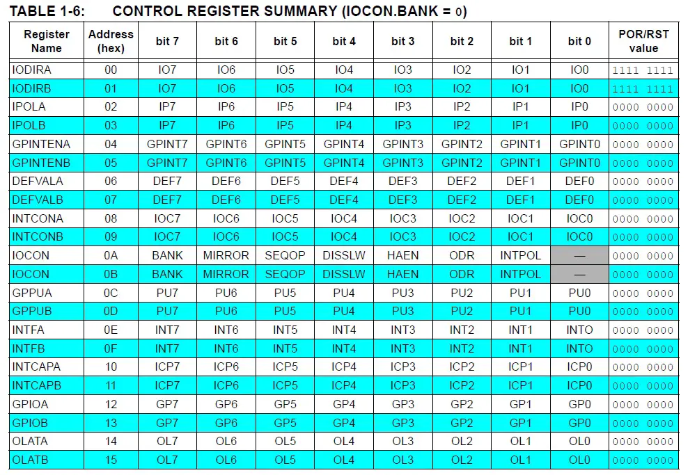
So after we have specified the direction (IODIRB) (0 = Output, 1 = Input), we want to let the three LEDs light up (Binary 00000111 = 0x07):
sudo i2cset -y 1 0x20 0x15 0x07
If we were to use the GPA pins, instead of 0x15, it would be 0x14.
For the LEDs to stop lighting, we need to reset the level of the pins to 0:
sudo i2cset -y 1 0x20 0x15 0x00
Raspberry Pi MCP23017 Python Script for Input and Output
So we create a script
sudo nano i2c_input_output.py
with the following content:
|
1 2 3 4 5 6 7 8 9 10 11 12 13 14 15 16 17 18 19 20 21 22 23 24 25 26 27 28 29 30 31 32 33 34 35 36 37 38 39 40 41 |
import smbus import time #bus = smbus.SMBus(0) # Rev 1 Pi bus = smbus.SMBus(1) # Rev 2 Pi DEVICE = 0x20 # Device Adresse (A0-A2) IODIRA = 0x00 # Pin Register fuer die Richtung IODIRB = 0x01 # Pin Register fuer die Richtung OLATB = 0x15 # Register fuer Ausgabe (GPB) GPIOA = 0x12 # Register fuer Eingabe (GPA) # Define GPA pin 7 as input (10000000 = 0x80) # Binary: 0 means output, 1 means input bus.write_byte_data(DEVICE,IODIRA,0x80) # Define all GPB pins as output (00000000 = 0x00) bus.write_byte_data(DEVICE,IODIRB,0x00) # Set all 7 output bits to 0 bus.write_byte_data(DEVICE,OLATB,0) # Function that makes all LEDs light up. def aufleuchten(): for MyData in range(1,8): # Count from 1 to 8, which is binary # from 001 to 111. bus.write_byte_data(DEVICE,OLATB,MyData) print "Zahl:", MyData, "Binaer:", '{0:08b}'.format(MyData) time.sleep(1) # Reset all pins to 0 again bus.write_byte_data(DEVICE,OLATB,0) # Endless loop waiting at the push of a button while True: # Read status of GPIOA register Taster = bus.read_byte_data(DEVICE,GPIOA) if Taster & 0b10000000 == 0b10000000: print "Taster gedrueckt" aufleuchten() |
Save and exit with CTRL + O and CTRL + X.
To start the script now, we enter
sudo python i2c_input_output.py
As soon as you press the button, the LEDs light up. By pressing CTRL + C you can cancel the script and return to the console.
As you can see, using it is pretty easy and you have created another 16 GPIO pins.
1 Comment
Hello,
Does this also works for Pi Rev. 3 B+?
Kind regards