
Acceleration and rotation sensors are most known from smartphones. The rotation of the device can be detected and can be addressed directly.
With the Raspberry Pi and a Gyroscope / Accelerator sensor it is possible to measure the rotation as well as the acceleration of the 3 axes.
In this tutorial I show how to use the MPU 6050 and how to read the values using I2C, which is demonstrated it in a video.
Components
For this tutorial I have used the following components:
- Raspberry Pi (US / UK)
- Acceleration sensor module (US / UK)
- Female-Female Jumper Kabel
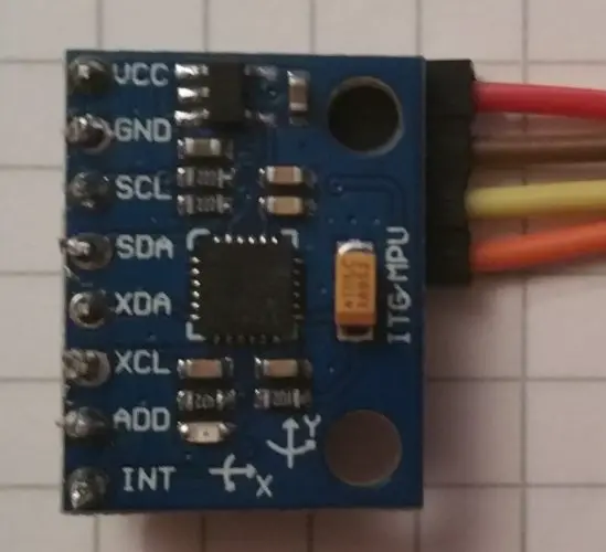
The module has 2 pin headers, one of those is bent. I’ve soldered the bent pins to the sensor board, which saves space (see picture):
Setup
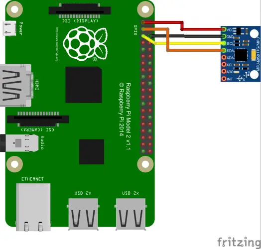
The practical thing about I2C is that very few pins are used. Of the eight pins of the sensor, we only need to connect the upper 4:
| Raspberry Pi | MPU 6050 |
|---|---|
| Pin 1 (3.3V) | VCC |
| Pin 3 (SDA) | SDA |
| Pin 5 (SCL) | SCL |
| Pin 6 (GND) | GND |
Activate I²C on the Raspberry Pi
First we enable SPI and I2C. If you have already done this in a previous tutorial, you can skip this step.
sudo raspi-config
Here we find the menu for activating services. Under “8. Advanced Options” there is the entry “A7 I2C”, which we activate (This can differ in other Raspbian versions). For older Raspbian versions, the entries in the /etc/modprobe.d/raspi-blacklist.conf file must be excerpted (with #).
We then edit the modules file:
sudo nano /etc/modules
If the following lines are not already included, add them and restart the Pi (sudo reboot):
|
1 2 |
i2c-bcm2708 i2c-dev |
Now we can quickly install the necessary tools:
sudo apt-get install i2c-tools python-smbus
Let’s start a small test. The parameter -y 1stands for revision 2. If you have a completely old Pi (before 2013), you would have to specify a 0 instead:
sudo i2cdetect -y 1
If the gyroscope is properly connected, you will see this output (if you have other I2C modules connected, their hex addresses should be displayed):
pi@raspberrypi ~ $ sudo i2cdetect -y 1
 0 1 2 3 4 5 6 7 8 9 a b c d e f
00: -- -- -- -- -- -- -- -- -- -- -- -- --
10: -- -- -- -- -- -- -- -- -- -- -- -- -- -- -- --
20: -- -- -- -- -- -- -- -- -- -- -- -- -- -- -- --
30: -- -- -- -- -- -- -- -- -- -- -- -- -- -- -- --
40: -- -- -- -- -- -- -- -- -- -- -- -- -- -- -- --
50: -- -- -- -- -- -- -- -- -- -- -- -- -- -- -- --
60: -- -- -- -- -- -- -- -- 68 -- -- -- -- -- -- --
70: -- -- -- -- -- -- -- --
To address the device with address 68 (Attention: Hexadecimal) under the register, enter the following:
sudo i2cget -y 1 0x68 0x75
Read the MPU-6050 Modul
The most convenient way to read the acceleration sensor is probably Python. Therefore, we create a file and paste the following code.
sudo nano gyro.py
|
1 2 3 4 5 6 7 8 9 10 11 12 13 14 15 16 17 18 19 20 21 22 23 24 25 26 27 28 29 30 31 32 33 34 35 36 37 38 39 40 41 42 43 44 45 46 47 48 49 50 51 52 53 54 55 56 57 58 59 60 61 62 63 64 65 66 67 68 69 70 |
#!/usr/bin/python import smbus import math # Register power_mgmt_1 = 0x6b power_mgmt_2 = 0x6c def read_byte(reg): return bus.read_byte_data(address, reg) def read_word(reg): h = bus.read_byte_data(address, reg) l = bus.read_byte_data(address, reg+1) value = (h << 8) + l return value def read_word_2c(reg): val = read_word(reg) if (val >= 0x8000): return -((65535 - val) + 1) else: return val def dist(a,b): return math.sqrt((a*a)+(b*b)) def get_y_rotation(x,y,z): radians = math.atan2(x, dist(y,z)) return -math.degrees(radians) def get_x_rotation(x,y,z): radians = math.atan2(y, dist(x,z)) return math.degrees(radians) bus = smbus.SMBus(1) # bus = smbus.SMBus(0) fuer Revision 1 address = 0x68 # via i2cdetect # Aktivieren, um das Modul ansprechen zu koennen bus.write_byte_data(address, power_mgmt_1, 0) print "Gyroskop" print "--------" gyroskop_xout = read_word_2c(0x43) gyroskop_yout = read_word_2c(0x45) gyroskop_zout = read_word_2c(0x47) print "gyroskop_xout: ", ("%5d" % gyroskop_xout), " skaliert: ", (gyroskop_xout / 131) print "gyroskop_yout: ", ("%5d" % gyroskop_yout), " skaliert: ", (gyroskop_yout / 131) print "gyroskop_zout: ", ("%5d" % gyroskop_zout), " skaliert: ", (gyroskop_zout / 131) print print "Beschleunigungssensor" print "---------------------" beschleunigung_xout = read_word_2c(0x3b) beschleunigung_yout = read_word_2c(0x3d) beschleunigung_zout = read_word_2c(0x3f) beschleunigung_xout_skaliert = beschleunigung_xout / 16384.0 beschleunigung_yout_skaliert = beschleunigung_yout / 16384.0 beschleunigung_zout_skaliert = beschleunigung_zout / 16384.0 print "beschleunigung_xout: ", ("%6d" % beschleunigung_xout), " skaliert: ", beschleunigung_xout_skaliert print "beschleunigung_yout: ", ("%6d" % beschleunigung_yout), " skaliert: ", beschleunigung_yout_skaliert print "beschleunigung_zout: ", ("%6d" % beschleunigung_zout), " skaliert: ", beschleunigung_zout_skaliert print "X Rotation: " , get_x_rotation(beschleunigung_xout_skaliert, beschleunigung_yout_skaliert, beschleunigung_zout_skaliert) print "Y Rotation: " , get_y_rotation(beschleunigung_xout_skaliert, beschleunigung_yout_skaliert, beschleunigung_zout_skaliert) |
Save it with CTRL + O and exit the editor with CTRL + X. You can then run the script.
sudo python gyro.py
Now you’ll see an output that contains all the captured data:
Gyroskop
--------
gyroskop_xout:   -260  skaliert:  -2
gyroskop_yout:   -154  skaliert:  -2
gyroskop_zout:     78  skaliert:  0

Beschleunigungssensor
---------------------
beschleunigung_xout:   -1048  skaliert:  -0.06396484375
beschleunigung_yout:    -676  skaliert:  -0.041259765625
beschleunigung_zout:   16644  skaliert:  1.01586914062
X Rotation:  -2.32121150537
Y Rotation:  3.59994842011
If you want to know more about accelerometers and gyroscopes, you should read this article.
Finally, a small sample video demonstrating the use of the sensor live:
25 Comments
What does 0x75 mean in the command:
sudo i2cget -y 1 0x68 0x75
The command that you send (hex)
0x75 is shown as WHO_AM_I (https://www.i2cdevlib.com/devices/mpu6050#registers)
Hi, I was going through this article to make a POC for my self and it was really helpful. I am very impressed by the video demonstration of the sensor and want to do similar thing where a image is mimicking the sensor movement on screen as shown in video.
Can you please provide me the code for that part as well ? I will really appreciate it. You can share the code at : sharma.swapn@gmail.com
I am sorry, the project is from some years ago. I don’t think that I have the code anymore 🙁
hai there, i am just trying this module and your tutorial is very helpful thank you. but can i ask? how u show the data on 3D? what software that you used. i this its more good if i can see data on 3D like your video.
hi there,,,
i a trying to run this code bus smbus is not working , error says that ” no module named as smbus”… can you help me out in this?
hi it works but I cant understand these lines of code
power_mgmt_1 = 0x6b
power_mgmt_2 = 0x6c
def read_byte(reg):
return bus.read_byte_data(address, reg)
def read_word(reg):
h = bus.read_byte_data(address, reg)
l = bus.read_byte_data(address, reg+1)
value = (h << 8) + l
return value
Can any explain where all the integer in the code came from?
for instance:
1. 8000 & 65535 in the “read_word_2c(reg)” function
2. 131 in “gyroskop_xout:”
3. 16384 in “beschleunigung_xout_skaliert”
This might be intuitive for someone with a strong background but I don’t have any clue on how to dig deeper for the meaning of those numbers. Anyone mind explaining would be very much appriciated
1. 0x8000 is a hexadecimal literal meaning 1000 0000 0000 0000 in binary, and 65535 is 2 to the 16th power minus one, making it the largest unsigned integer than can be encoded in 16 bits. This is being done because the bus data is in two’s complement (hence the “2c” in “read_word_2c”)
2 & 3. I believe these are conversions from the 16 bit output to readable output
I am trying to interface the mpu 650 module to node mcu to calibrating the values for robot i am
trying to useed the display the calibrating values (X-Y axis) please provide the code for node mcu.
thankyou.
link: http://bigbelectronics.in/product.php?product=gy-521-mpu6050-module-3-accelerometer-arduino
Hello,
I’m trying to connect two MPU9250 in my rapsberry pi. So i’m trying to change the address of one MPU. I had connected the AD0 pin to 3.3V but it’s still in the 0x68 direction. Should i do something more??
Hello,
my return values are all zero, checked twice connection, prerequisites and code.
Rpi2b
Any Idea
I have a problem with MPU6050 gyro sensors, I am making school project with Vehicle Accident GPS tracking. When the normal condition, eventhing is ok. Gyro is working his axis,but when over limit gyro’s x,y,z values, LCD and Serial monitor is stop their process. how can i do that?
link: bigbelectronics.in/product.php?product=gy-521-mpu6050-module-3-accelerometer-arduino
hi, i am working with accelerometer output of anroide mobile like that
x = 1.0
y = 1.30
z = 9.4
using this data how can i predict that
1. mobile is in vertical position or not
2. mobile is falling down
3.mobile get carry out by human
do you need to solder the parts together
only if the chip does not already have the pins soldered on – if the pins and the chip are separate pieces than yes
I am not getting accelerometer data at all :
Gyroskop
——–
gyroskop_xout: 2 skaliert: 0
gyroskop_yout: 26 skaliert: 0
gyroskop_zout: 3 skaliert: 0
Beschleunigungssensor
———————
beschleunigung_xout: 0 skaliert: 0.0
beschleunigung_yout: 0 skaliert: 0.0
beschleunigung_zout: 0 skaliert: 0.0
X Rotation: 0.0
Y Rotation: -0.0
Can you please help
I am not getting accelerometer data at all :
Gyroskop
——–
gyroskop_xout: 2 skaliert: 0
gyroskop_yout: 26 skaliert: 0
gyroskop_zout: 3 skaliert: 0
Beschleunigungssensor
———————
beschleunigung_xout: 0 skaliert: 0.0
beschleunigung_yout: 0 skaliert: 0.0
beschleunigung_zout: 0 skaliert: 0.0
X Rotation: 0.0
Y Rotation: -0.0
Same problem.
Did you solve?
same problem did you solve ?
Here Z-axis rotation is not there. Why you don’t calculate that?
Hello, great article. I have a question about the other pins on MPU6050. I cannot directly use the MPU6050 directly with my GPIO pins on the Jetson Nano and so I am going to need to use level shifters. But I do not know which shifters to get, 8 channel or 4 channel. The MPU6050 has 8 pins which led me to the 8 channel but then you mentioned only needing 4 of the pins. Is this only with I2C interface or can I also only use 4 pins with the IIC interface.
sorry forget the last line, lol