 with a Raspberry Pi")
To use, for example, a weather station, it is important to know the brightness. With a Raspberry Pi light sensor (photoresistor/brightness sensor), it is very easy to determine a value, which can say, for example, if it is day, twilight or night.
In turn, projects could be implemented to control the (exterior) lights, which turn on automatically after a certain level of darkness. In this tutorial, we connect such a brightness sensor and read the light values accordingly, so that we can respond.
Required Hardware Parts
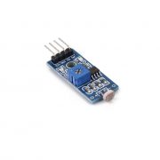
The photoresistor used is in addition to the actual version on a PCB (circuit board), whereupon et al. resistors are soldered. As a result, it is additionally possible to read out a digital signal which stands for “above/below the threshold value”. Reading this digital signal is very easy and will be covered in some other tutorials (for example here). Both versions can be used with this tutorial, only the one version just has an additional functionality. For projects like distinguishing between light/dark, it is certainly a simple alternative.
The following components are necessary for this tutorial:
- Raspberry Pi 3 or similar
- Photoresistor
- Alternative Photoresistor as a Module
- MCP3008
- 10kΩ resistor
- Breadboard
- Jumper Cable
If you’re interested in how photoresistors (LDRs) work in general, you can read more about them here. In general, it can be said that the resistance changes are depending on the brightness.
Connect Raspberry Pi Light Sensor
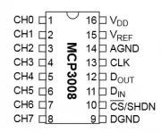
However, before we can connect and read the phototransistor, we need to connect an analog-to-digital converter. In addition, you can find here a quite detailed article about the MCP3008, which we also use in this tutorial. In order not to inflate this article unnecessarily, I will not go into detail on the MCP3008. The exact connection between ADC and Raspberry Pi can also be found in another article.
It is important that the brightness sensor also has a connection (via a 10kΩ resistor) to the ground connection, otherwise, the value cannot be clearly read out. If there is no voltage at all coming through the LDR, then it is at 0 (due to the connection to GND). If the voltage is flowing, a part goes back through the 10kΩ resistor, but this part is very low because the resistance is large. As with other resistors, it does not matter on which side the positive voltage is applied to the photoresistor.
Schematically, the structure looks like this:
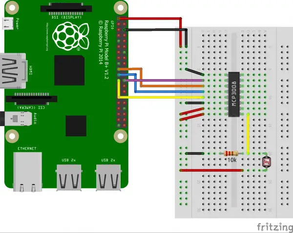
If you later see fairly high levels even with low light, you can add extra resistance between the positive voltage and the pin of the light sensor.
If you are using a soldered photoresistor, you only need 3.3V (Pin 1) from the Raspberry Pi to VCC and GND and GND (Pin 6) from the Pi. Pin A0 is connected directly to the analog-to-digital converter. Thus, no 10k pull-up resistor is needed. The advantage is that you can set the series resistor by a potentiometer (rotational resistance) individually – depending on the maximum brightness.
Read Brightness Sensor on the Raspberry Pi
In the other tutorial for the MCP3008, we have created a class, which we will also use here. Make sure that SpiDev is installed as described. As a reminder, you will find the content of the class here again:
|
1 2 3 4 5 6 7 8 9 10 11 12 13 14 15 16 17 18 19 20 21 |
from spidev import SpiDev class MCP3008: def __init__(self, bus = 0, device = 0): self.bus, self.device = bus, device self.spi = SpiDev() self.open() self.spi.max_speed_hz = 1000000 # 1MHz def open(self): self.spi.open(self.bus, self.device) self.spi.max_speed_hz = 1000000 # 1MHz def read(self, channel = 0): adc = self.spi.xfer2([1, (8 + channel) << 4, 0]) data = ((adc[1] & 3) << 8) + adc[2] return data def close(self): self.spi.close() |
If this class exists in the current directory, you can simply open the Python console via sudo python (or alternatively create a script) and enter:
|
1 2 3 |
from MCP3008 import MCP3008 adc = MCP3008() print( adc.read( channel = 0 ) ) # if necessary perform several times |
With me, complete darkness (fingers held on it) gave a value of approximately 600, which means that approximately 1.95V voltage came from the original 3.3V to the MCP3008. At brightness I had permanently a value of 1023.
The maximum resistance varies slightly depending on the light resistance. If the brightness is very high (daylight) we recommend a series resistor or another pull-resistor (previously 10k).
2 Comments
If you are frugal then you can also use these with just a capacitor, maybe 50uF 6V, taken from waste electronics.
Connect the photoresistor in parallel with the capacitor and connect between the GPIO port and ground. Make the GPIO port an output and send a 1/high/True for a few tens of milliseconds to charge the capacitor. Then make it an input and poll it until it turns from True to False. The brightness makes this time longer.
With Raspbian, that method will have a lot of bounce as other tasks interrupt the polling loop and short the count. To get any reliability, you have to use threads, an interrupt on level change, and the 1MHz system clock. Using a MCP3008 might be less hassle.
Still, if you only need a general dark/light range, taking several readings and smoothing them might work.