")
In some applications, it is important that the Pi continues to be powered in the event of a power outage. If something is written on the SD card at the moment of power interruption, it is possible that the image will become corrupt and thus unusable.
A UPS (Uninterruptible Power Supply) ensures that if a power interruption occurs, a battery/another power source will intervene without affecting the unit.
Such an UPS can be easily created with a few components and in a case of emergency a script will respond to it and shut down the Pi properly.
Required Hardware Parts
- Powerbank with 2.1A output (important: must be simultaneously loadable and unloadable)
- USB hub (otherwise a cable would have to be cut)
- Relay
- 10kΩ resistor
- 2 micro USB cables
- Jumper cable
Although there already are ready to buy UPS for the Raspberry Pi, these are either quite expensive (link) or not rated very well (link). Another variant (which, however, requires soldering and electronics skills), would be the supply of two power sources – one via the socket and the other via the powerbank.
Setup
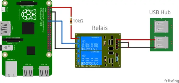
1 – VCC (5V)
4 – GND
© hardwarelabs.de
Two USB ports of the hub are required. At the first, the power bank is connected, which will serve the Pi as a power source. The second USB port is used as the on/off switch for the relay. I simply clamped the cables that control the relay under the brackets. On the right side, you can see where 5V and GND are connected to a USB port.
The middle OUT pin of the relay comes to GPIO27 (pin 13) of the Pi. The right OUT pin is connected to pin 2 (5V) of the Pi via a 10kΩ resistor and pin 6 (GND) to the right.
Software
Suppose there comes to a power failure. For one thing, the Pi would still run for a few hours (depending on the power bank model). But then it would be over. In order for the Pi to be informed that it is currently running on “emergency power”, the relay switches at and on GPIO23 are now 0V. Before that, there was a high level because the USB hub power supply also had the relay open.
In my example, I want to show how to respond to the change and shut down the Pi properly. Of course, other actions can be performed (send email, save data, drive down after a while, etc.).
For this example, you need to have wiringPi installed (a similar implementation with Python should certainly be possible). The wiringPi pin 2 corresponds to GPIO27 (see wiringPi pin assignment).
We will create a new file
sudo nano /usr/local/etc/USV.sh
with the following content:
|
1 2 3 4 5 6 7 8 9 10 11 12 13 14 15 16 17 18 |
#!/bin/bash gpio mode 2 in while true do result="$( gpio read 2 )" if [ "$result" = "1" ]; then # Custom Code # in 60 min shut down sudo shutdown -h 60 & # Custom Code End fi sleep 1 done |
Instead of my code, any other shell command can be entered.
So that the script now also starts with each reboot, we enter it as crontab:
sudo crontab -e
The following line will be added at the end of the file:
@reboot bash /usr/local/etc/USV.sh &
The Powerbank model I use shuts off its charge as soon as it’s full. If interested, I can also present a circuit, which allows you to recharge the power bank every X hours (which is basically just an additional relay). For that, you can also read this article if necessary.
9 Comments
I am interested in the last part of this tutorial. However there seems to be a link missing in the final sentence. I can guess at what’s needed but it’s always good to hear from the experts. I have a concern about leaving batteries permanently on charge so a set up that recharges, say, every hour seems safer to me.
what is the difference if we take a relay to a channel
Hello,
I do not understand how this works. If the USB hub is the only responsible part that controls the relay, how is it possible for the power bank to signal the loss of main power ?
On the other hand, if the Pi is powered through its dedicated mini-USB port, the loss of main power would switch the Pi off immediately, without any chance for it to commute to the power bank source.
Could you please explain to me how your UPS works ? Thanks.
Regards
RC
I think PI is powered from power bank not main power while USB port controlling relay is powered from main power.
IMHO weakness of this design is what happen when main power is back on. Since PI connected to power bank it wont re-start automatically.
Possible solution is to add another relay controlled by main power to disconnect and re-connect power bank after main power is back on.
Hello, I have a question about your circuit. In your circuit it can only judge that the power has been used up. Does this mean that you use parallel circuits in Raspberry and powerbank?
What makes you sure that the power signal, given by the switching off of the relay comes in time?
Typically a relay once powered has a big hysteresis to switch back into unpowered position.
Why don’t you simply measure the analog voltage of the powerbank with the gpio?
Relays is how the term is spelled….not relais
This has some good ideas, however, without the power bank in the diagram, it is nearly pointless. The relay that switches the GPIO between V and Ground is a good idea, but should be connected to a 3.3 pin, not a 5v pin, regardless of the resistor. The power bank should be getting its supply from the USB hub, but we don’t see that in the diagram. A serious flaw in the script is starting the shutdown command with a 60 minute delay, this is foolish as power could be restored within that time frame. Instead, a timer in the script should be started that would check for power after 60 (or however many minutes) and then shut down. That timer would be stopped/deleted if power was restored. As others have pointed out, there is no hardware to cause a restart.
relais – is French for relay. Schematic is in French