")
One of the special features of the Raspberry Pi is the programmable input-output pins. These so-called GPIOs can easily be switched via a program, which we will go through in this tutorial. For this we will write a Python program, on the one hand, we record inputs and on the other hand, we switch the Raspberry Pi GPIO pins so that we can switch other modules and sensors. In addition, I will also explain how a breadboard works.
If you have not read the first part and you still have problems with the basics, I would advise you to go through that one first. For those who already have programming experience but have not yet worked with the GPIOs, you can start with this directly.
By the way: It would be great for the other parts if you have any suggestions or what interests you the most. I will try to incorporate that in the future.
Required Hardware Parts
In this tutorial, we will need a few hardware building blocks. These are among others:
- Breadboard, the functionality of which is explained below.
- Male-female jumper cable for the connection between Raspberry Pi and the breadboard.
- LED Set
- Push-button/switch
- Resistor set
Incidentally, these components are always needed. If you want to build more hardware projects, you will definitely need these accessories.
How does a Breadboard work?
A breadboard is helpful as by using it one is able to set up circuits quickly without having to solder them every time. It offers great advantages especially when testing and designing. There are breadboards in different sizes, but the structure is usually as follows:
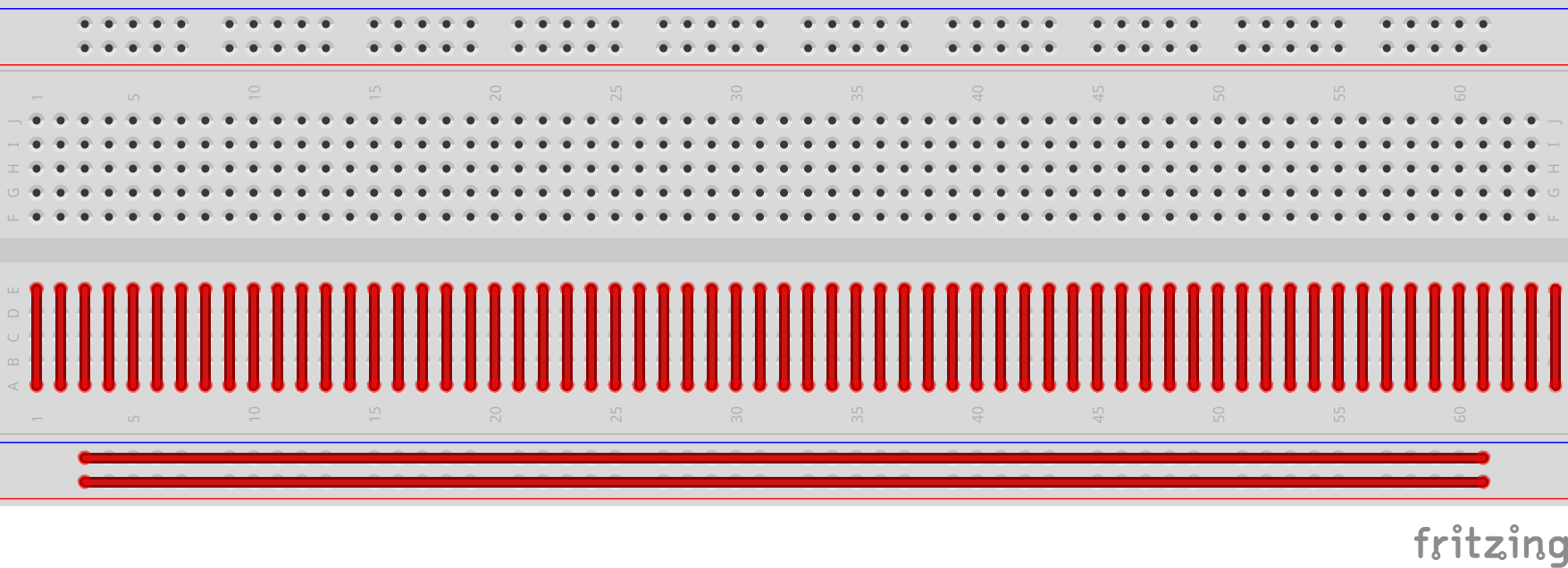 The connections are marked in the schematic drawing below. The lines show which of the holes are connected. At the top and on the bottom, you can see two horizontal bars, to which you normally attach the plus and minus pole of a device.
The connections on the middle pins are vertical. Here, e.g. an LED can be inserted in two columns next to each other. But more on that in a moment.
Raspberry Pi GPIO Overview
Since model B +, the Raspberry Pi’s have a 40-pin header. Not all of them can be read out or connected as there are also some voltage and ground connections. The following graphic lists the complete pins including functions and numbering. The left (green) side should symbolize the board of the Raspberry Pi.
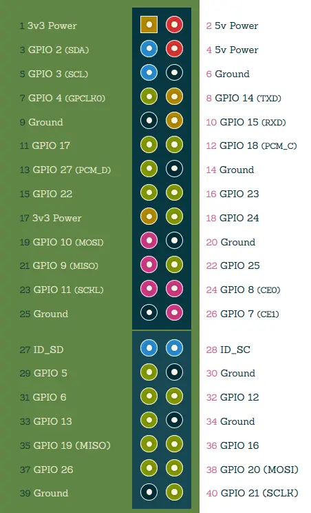
All pins that have “GPIO” in their names can be programmed. There is also “Ground” (= ground connection) and the voltage pins (3.3V and 5V).
As you can see, there are two pin assignments: First the ascending pin assignment (starting at 1 in the top left) and then the rather random numbering of the GPIOs. This is important because you can address a GPIO via both numbers.
Pin 15 = GPIO 22, for example. Always pay attention to whether pin or GPIO is used. Most tutorials do not use the pin numbering, but the GPIO number.
Preparation
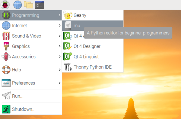
As before, we open the Python editor via the Start menu > Programming.
In the opened Python console we first enter the following:
import RPi.GPIO as GPIO
We are importing a library with which we can program the Raspberry Pi GPIO pins. This library already contained all the required functions, so we do not have to write any additional functions for it.
We also import a library with which we can stop the script for a short time. This will be interesting afterwards.
import time
Then we indicate whether we want to address the GPIOs via board numbers (1-40) or via their GPIO number. Since we want the latter, the command is:
GPIO.setmode(GPIO.BCM)
Switch Raspberry Pi GPIO Pins – Output
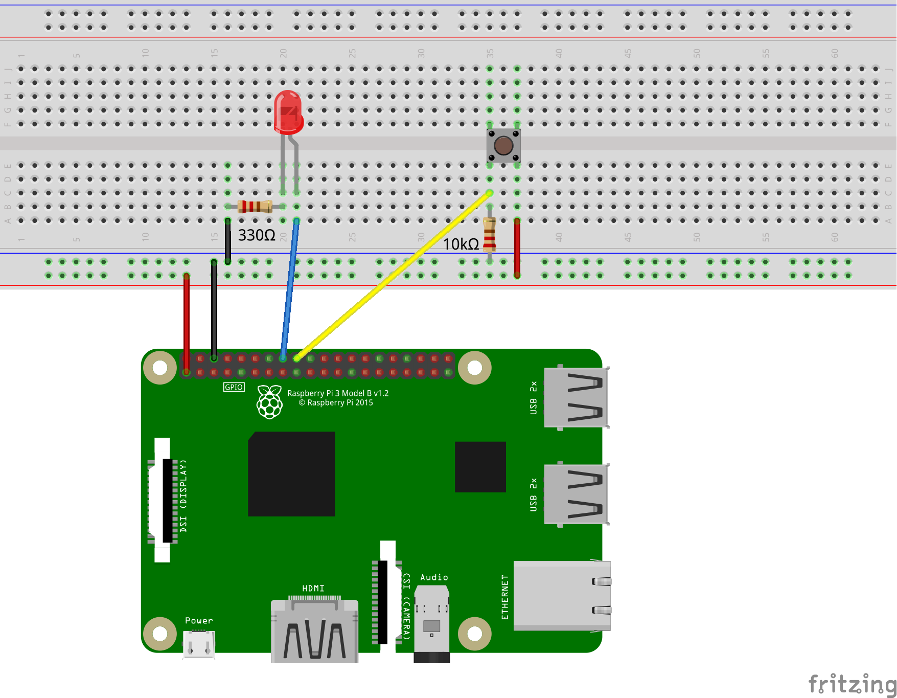
First of all, we want to switch a few simple LEDs using the GPIOs. We build the LEDs according to the following graphic. As a connection between the Raspberry Pi and the breadboard, you can use the jumper cables and simple wire for all other connections. The colours are irrelevant and are only intended for better differentiation.
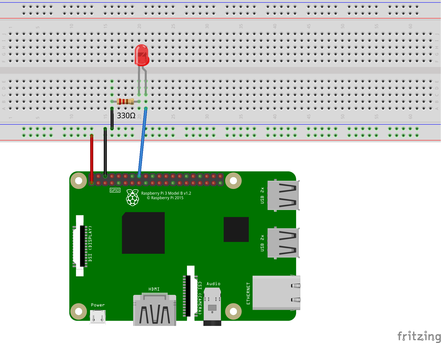
The LED has two ends of different lengths. The longer end comes to the positive 3.3 volt voltage of the GPIO 23 (pin 16). The chosen resistance is 330Ω (Ohm).
Now it goes back to the Python console, where we enter our code. First of all, we have to define the pin as output:
GPIO.setup(23, GPIO.OUT)
The output functions for this pin are now available. With the following two commands we can firstly switch the LED on and then switch it off again:
GPIO.output(23, GPIO.HIGH)
GPIO.output(23, GPIO.LOW)
This command simply says whether a voltage of 3.3V (HIGH) or 0V (LOW) should be applied.
It’s pretty easy, isn’t it?? If you want to build a small flashing circuit, you can e.g. do the following:
for i in range(5):
    GPIO.output(23, GPIO.HIGH)
    time.sleep(0.5)
    GPIO.output(23, GPIO.LOW)
    time.sleep(0.5)
This turns the LED on and off 5 times, waiting for half a second in between before changing the status.
Read out Raspberry Pi GPIO Pins – Input
With the GPIOs, currents can not only be switched, but they can also be read out. Therefore, we are now expanding our circuit with a button. The status should be read and the LED should light up as soon as the button is pressed. If the button is no longer pressed, the LED should also stop lighting up.
Firstly we expand the circuit. In addition to the button, we need a 10,000Ω resistor, which is connected to ground from one end of the button. In between, there is a connection to the GPIO 24 (pin 18). The other end of the switch is connected to the 3.3 volt voltage:
Why the whole thing? As long as the switch is not pressed, the connection between the 3.3V voltage and the GPIO is open. However, in order for a clear state to be recognized (either 0V or 3.3V), the connection is connected to the ground connection via a very large resistor.
As soon as the button is pressed, the connection closes and 3.3V is connected to the GPIO.
Note: Never connect more than 3.3V to the GPIOs, otherwise they can break.
Let’s get to the code. Here, too, we first have to set the status, but this time the pin is defined as input:
GPIO.setup(24, GPIO.IN)
Now we can already query the status:
GPIO.input(24)
This will either output 0 (if the button was not pressed) or 1 (if the button was pressed).
In the last step, we extend the program as follows, so that the LED is always on when the button is pressed.
# Infinite loop
while True:
    if GPIO.input(24) == 0:
        # Turn off
        GPIO.output(23, GPIO.LOW)
    else:
        # Turn on
        GPIO.output(23, GPIO.HIGH)
You can also cancel the process with CTRL + C.
Summary
In summary, there is also the code of the entire script in case someone wants to save it in a file and call it as a whole.
import RPi.GPIO as GPIO
import time

GPIO.setmode(GPIO.BCM)

GPIO.setup(23, GPIO.OUT)
GPIO.setup(24, GPIO.IN)

for i in range(5):
    GPIO.output(23, GPIO.HIGH)
    time.sleep(0.5)
    GPIO.output(23, GPIO.LOW)
    time.sleep(0.5)

# Infinite loop
while True:
    if GPIO.input(24) == 0:
        # Turn off
        GPIO.output(23, GPIO.LOW)
    else:
        # Turn on
        GPIO.output(23, GPIO.HIGH)
If you enjoyed this introduction, I can only recommend the mini project of a traffic light switch. Divided into two parts, a functioning traffic light system consisting of car and pedestrian lights is built.
You can find more information about this structure here.
With the knowledge imparted here, you can already start small projects. Here’s a little taste:
- Raspberry Pi: Control Relay Switch via GPIO
- Measuring Temperature with a Raspberry Pi Temperature Sensor (1-Wire)
- Raspberry Pi Traffic Light Circuit with GPIO Part 1
- continuing also: Expand Raspberry Pi GPIOs with I2C Port Expander
In the next part we will write our first GUI (Graphical User Interface), which we can also use to control the GPIOs.
3 Comments
Resistor on LED should be connected to signal control, not to ground
Ohm’s Law caters for both locations without any difference in operation. Current in a series circuit will be the same no matter where the current reading is taken. This excludes paralleled circuits where the Circuit is a Current Divider.
I’m curious why you said that…