In addition to many other interesting projects with the Pi, a self-made robot is a small highlight because it brings together many components. In the following parts, we will create a robot with many (independent) functions step by step.
In the first part of the Raspberry Pi robot tutorials, we will assemble the kit and create functions for controlling the motors, with which the robot can already drive in all directions. These are required in the following parts when we use our robot e.g. remote control or want it to follow a line.
Kit and Required Hardware Parts
It is advisable to take a kit that already contains the most necessary things. I used a kit with two controllable wheels, but there are also those with 4 wheels. I would recommend beginners, if you want to follow the tutorial exactly, to use the same kit – but it shouldn’t be too much effort to adapt the code for four-wheel bodies.
In this tutorial I used the following, because in addition to the kit itself, i.a. a motor driver IC is required:
- Robot kit with 2 wheels
- L293D IC
- 4xAA batteries (1.5V)
- Powerbank (my recommendation: Aukey)
- alternatively: LM2596 voltage regulator
- Mini breadboard
- Jumper cable
- Soldering utensils (soldering iron, solder, pad, etc.)
Which Raspberry Pi model is used does not matter. A Raspberry Pi Zero is practical because it is light and takes up little space, but extensions (such as USB cameras) are difficult to attach later.
Build the Raspberry Pi Robot Kit
In addition to the wheels and motors, the kit comes with some screws and plates, which we will assemble. The included parts of the two-wheel kit are as follows:
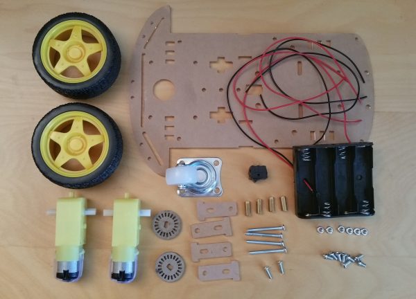
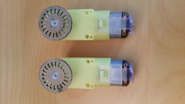
First we will screw the motors tight. To do this, we take the two motors and attach the cogs to them:
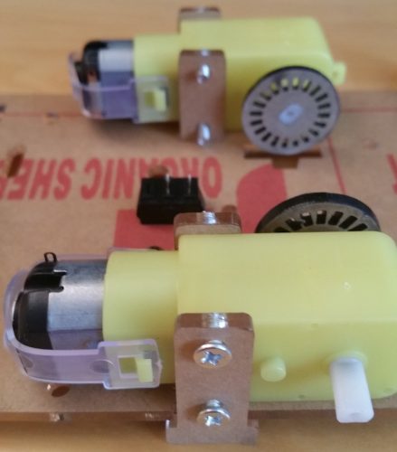
With the help of the 4 long screws and the 4 smaller plates, the motors are attached to the large plate. For this purpose, a plate is pushed through the appropriate hole on both sides in the middle. The engine is placed next to it. Care must be taken that the connections of both motors point inwards.
The remaining two plates are placed on the outer sides and the long screws (from the outside) are inserted. The small nuts are attached on the inside and thus the motors are fastened.
If you want to use the batteries instead of a power bank, you can still insert the switch in the central hole.
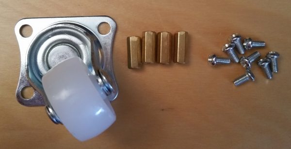
Next the front wheel is attached. We take the rotating wheel, the 4 spacers and 8 screws. I recommend oiling the bike a little before attaching it as it is sometimes difficult to move.
The four spacers are first screwed to the wheel. Then they are attached to the front of the plate with the remaining screws. You can also attach the rear wheels to engines.
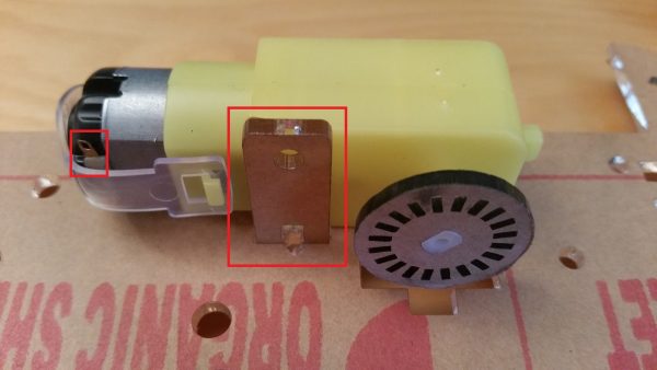
Now only two cables have to be soldered to the “tabs” (see the 2nd picture and the 3rd picture, left side) of the motor, which requires a little sensitivity. If you want to test the motors, you can then attach a cable to 3.3V (pin 1) of the Raspberry Pi and one to GND (pin 6). The motor should now move (whether forwards or backwards doesn’t matter at first).
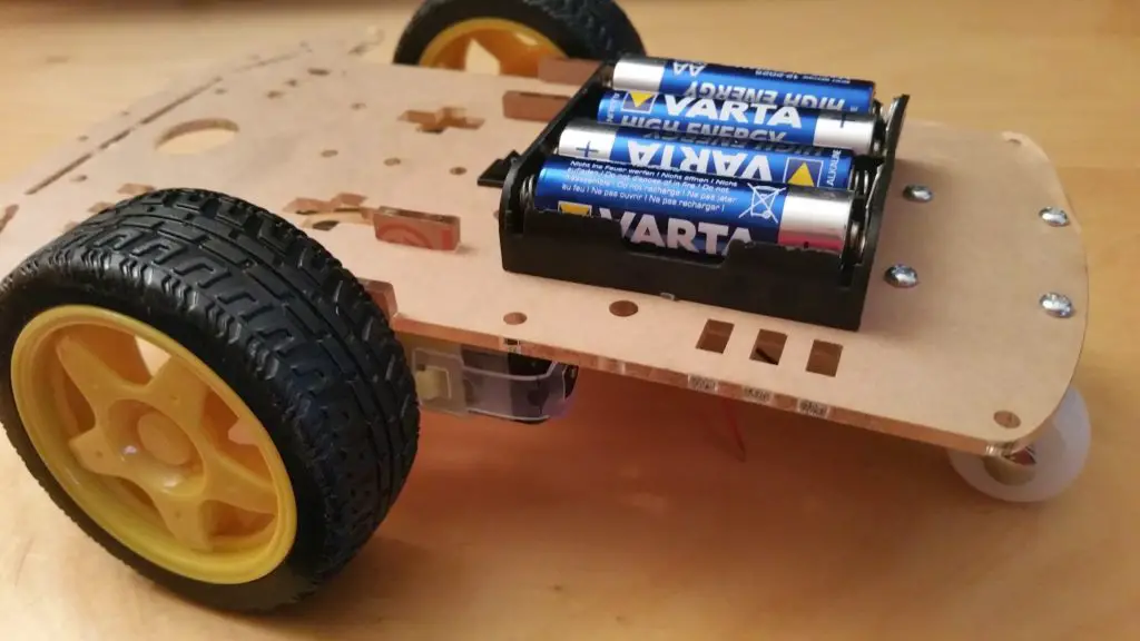
The last step is not just for those who want to use batteries, as the motors need more power than the Raspberry Pi can provide. To do this, the battery holder must be attached to the front top of the plate with the remaining two screws and nuts. The cables can be laid down through the small round hole in the middle:
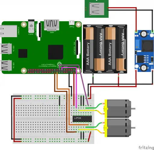
In order to use the batteries as a voltage source for the Pi, you need the voltage converter LM2596. This adjusts the voltage to 5V (for the tutorial). You can connect the switch between the USB port and the voltage converter in order to be able to interrupt the power supply if necessary. For the sake of simplicity, however, I use a power bank for powering the Pi. In the schematic structure, the voltage converter is still available for the sake of completeness. The voltage for the motors comes from the batteries.
Connection of the Motors
In order to be able to run the two DC motors forwards and backwards, we need the motor driver IC (L293D). This can control 4 channels, so it is perfect for our two DC motors. In the following schematic structure you can see the connections:
The exact functioning and cabling are also among others described in this tutorial, so I won’t go into that here. As GPIO pins for the left motor, I use 17 and 27 and 23 and 24 for the right motor. Make sure that the external power supply (batteries) is used since the 5V pin of the Pi is not sufficient (motors will only rattle).
Code For Moving the Robot
Finally, before the robot takes its first steps, the corresponding code is still missing. For this, I wrote a class which is also used in the following parts.
We create a folder in which all files of the robot come in and create the file in which the code for the motor comes:
sudo mkdir RaspberryPi-Robot
cd RaspberryPi-Robot
sudo nano l293d.py
The file gets the following content:
|
1 2 3 4 5 6 7 8 9 10 11 12 13 14 15 16 17 18 19 20 21 22 23 24 25 26 27 28 29 30 31 32 33 34 35 36 37 38 39 40 41 42 43 44 45 46 47 48 49 50 51 52 53 54 55 56 57 58 59 60 61 62 63 64 65 66 67 68 69 70 71 72 73 74 75 76 77 78 |
import RPi.GPIO as GPIO import time import threading #GPIO.setmode(GPIO.BCM) #GPIO.setwarnings(False) class L293D(): DIST_PER_SEC = 35.0 # cm/s SEC_PER_TURN = 2.087 # seconds per full turn (depending on the base material, use forwardLeft(), stop() and time.time() to measure the time) def __init__(self, left_pin1, left_pin2, right_pin1, right_pin2): self.MOTOR_LEFT_PIN1 = left_pin1 self.MOTOR_LEFT_PIN2 = left_pin2 self.MOTOR_RIGHT_PIN1 = right_pin1 self.MOTOR_RIGHT_PIN2 = right_pin2 GPIO.setup(self.MOTOR_LEFT_PIN1, GPIO.OUT) GPIO.setup(self.MOTOR_LEFT_PIN2, GPIO.OUT) GPIO.setup(self.MOTOR_RIGHT_PIN1, GPIO.OUT) GPIO.setup(self.MOTOR_RIGHT_PIN2, GPIO.OUT) def forwardLeft(self): GPIO.output(self.MOTOR_LEFT_PIN1, GPIO.LOW) GPIO.output(self.MOTOR_LEFT_PIN2, GPIO.HIGH) GPIO.output(self.MOTOR_RIGHT_PIN1, GPIO.LOW) GPIO.output(self.MOTOR_RIGHT_PIN2, GPIO.LOW) return time.time() def forwardRight(self): GPIO.output(self.MOTOR_RIGHT_PIN1, GPIO.LOW) GPIO.output(self.MOTOR_RIGHT_PIN2, GPIO.HIGH) GPIO.output(self.MOTOR_LEFT_PIN1, GPIO.LOW) GPIO.output(self.MOTOR_LEFT_PIN2, GPIO.LOW) return time.time() def forward(self): GPIO.output(self.MOTOR_LEFT_PIN1, GPIO.LOW) GPIO.output(self.MOTOR_LEFT_PIN2, GPIO.HIGH) GPIO.output(self.MOTOR_RIGHT_PIN1, GPIO.LOW) GPIO.output(self.MOTOR_RIGHT_PIN2, GPIO.HIGH) return time.time() def backwardLeft(self): GPIO.output(self.MOTOR_RIGHT_PIN1, GPIO.HIGH) GPIO.output(self.MOTOR_RIGHT_PIN2, GPIO.LOW) GPIO.output(self.MOTOR_LEFT_PIN1, GPIO.LOW) GPIO.output(self.MOTOR_LEFT_PIN2, GPIO.LOW) return time.time() def backwardRight(self): GPIO.output(self.MOTOR_RIGHT_PIN1, GPIO.HIGH) GPIO.output(self.MOTOR_RIGHT_PIN2, GPIO.LOW) GPIO.output(self.MOTOR_LEFT_PIN1, GPIO.LOW) GPIO.output(self.MOTOR_LEFT_PIN2, GPIO.LOW) return time.time() def backward(self): GPIO.output(self.MOTOR_LEFT_PIN1, GPIO.HIGH) GPIO.output(self.MOTOR_LEFT_PIN2, GPIO.LOW) GPIO.output(self.MOTOR_RIGHT_PIN1, GPIO.HIGH) GPIO.output(self.MOTOR_RIGHT_PIN2, GPIO.LOW) return time.time() def stop(self): GPIO.output(self.MOTOR_LEFT_PIN1, GPIO.LOW) GPIO.output(self.MOTOR_LEFT_PIN2, GPIO.LOW) GPIO.output(self.MOTOR_RIGHT_PIN1, GPIO.LOW) GPIO.output(self.MOTOR_RIGHT_PIN2, GPIO.LOW) def forwardDistance(self, dist): self.forward() threading.Timer(dist/self.DIST_PER_SEC, self.stop) def backwardDistance(self, dist): self.backward() threading.Timer(dist/self.DIST_PER_SEC, self.stop) |
With CTRL + O, CTRL + X we save and close the editor. We start a first test in which the robot moves a few centimeters and turns in a circle:
sudo python
|
1 2 3 4 5 6 7 8 9 10 11 12 13 14 15 16 |
import RPi.GPIO as GPIO import time from l293d import L293D GPIO.setmode(GPIO.BCM) GPIO.setwarnings(False) l = L293D(17,27,23,24) l.stop() for i in range(20): l.forward() time.sleep(0.5) l.forwardRight() time.sleep(0.5) l.stop() |
If the functions do not work as they should (drives backwards instead of forwards, etc.) just swap the two cables of the motor and test again. The GPIO assignment must, of course, be adjusted if it differs from the assignment used here.
Adjust the Motor Parameters
For the other parts, it is important that the two parameters DIST_PER_SEC and SEC_PER_TURN are specified correctly. However, these depend on the surface (carpeting, parquet, tiles, etc.) and must, therefore, be measured individually. To measure DIST_PER_SEC following command is sufficient:
l.forward();time.sleep(1.0);l.stop()
Then you can simply measure the distance travelled and enter the value (in centimeters).
A little skill is required to measure SEC_PER_TURN. For this, we start one of the motors and stop as soon as a 360° turn is finished. Here you have to play with the waiting period until you find a good value:
waiting period = 2.08
l.forwardLeft();time.sleep(wartezeit);l.stop()
Afterwards, both values have to be adjusted in the file.
In the next part, we will let the robot follow a line.

