
In projects such as the automated greenhouse, it is important to know how much water, for example, reaches the plants for irrigation. There is also an inexpensive variant that we can quickly read using the Python programming language and also integrate into our smart home system. We can query the Raspberry Pi Water Flow Sensor at any frequency (e.g. every second) to determine how many litres flow through it per second or minute.
You can find the exact setup and the code for it in this tutorial.
Required Hardware Parts
Depending on the project, you will be using a few other hardware parts. In this tutorial, however, we will limit ourselves to reading out the sensor and will therefore only assume the parts that are absolutely necessary. These are:
- Raspberry Pi
- Water flow sensor (model YF-S201)
- Jumper cables
- optional: water pump (voltage depends on the required power)
In order to be able to connect a hose, we need a so-called tap connector. There are two ways to do this:
- Print it yourself (3D printer required) with the help of this file
- Buy it (half inch)
Connection of the Water Flow Sensor YF-S201 to the Raspberry Pi
In the data sheet of the sensor we find different information, of which the most important are:
- Input voltage: 3.5 – 24V
- Flow Range: 1-30 litres per minute
- F = 7Q (L/MIN)
- Sample frequencies:
- 2L/MIN=16HZ
- 4L/MIN=32.5HZ
- 6L/MIN=49.3HZ
- 8L/MIN=65.5HZ
- 10L/MIN=82HZ
- a single signal pin (yellow)
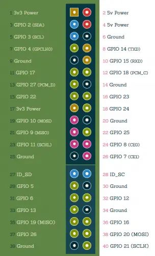
The connection to the Raspberry Pi using a jumper cable is easy thanks to the three pins:
- GND (black) to GND (Pin 6)
- VCC (red) to 3.3V (Pin 1)
- Signal (yellow) an GPIO 13 (Pin 33)
Although at least 3.5V is required according to the data sheet, I was able to read the signal successfully even at 3.3V. If this is not possible, you can use 5V and put a larger resistor between the signal output and the GPIO.
In principle, any other free GPIO pin can also be used:
Now all that remains is the connection of the hoses. We need the tap connector for the flow meter, which we can best print ourselves:
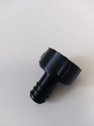
If you are using a different Raspberry Pi Water Flow Sensor, then pay attention to the description. The one used here had the following information:
- Inside diameter: 11 mm
- Outer diameter: 20 mm
Accordingly, a part can be easily edited using tools such as Tinkercad. The same also applies to hose connections: If you want to connect water hoses with different dimensions, you can print these connectors yourself.
Reading out Raspberry Pi Water Flow Sensor via Python
We now create a new Python script with the following content:
sudo nano water_flow.py
|
1 2 3 4 5 6 7 8 9 10 11 12 13 14 15 16 17 18 19 20 21 22 23 24 25 26 27 28 29 30 31 32 33 34 35 36 |
#!/usr/bin/python import RPi.GPIO as GPIO import time, sys #import paho.mqtt.publish as publish FLOW_SENSOR_GPIO = 13 #MQTT_SERVER = "192.168.1.220" GPIO.setmode(GPIO.BCM) GPIO.setup(FLOW_SENSOR_GPIO, GPIO.IN, pull_up_down = GPIO.PUD_UP) global count count = 0 def countPulse(channel): global count if start_counter == 1: count = count+1 GPIO.add_event_detect(FLOW_SENSOR_GPIO, GPIO.FALLING, callback=countPulse) while True: try: start_counter = 1 time.sleep(1) start_counter = 0 flow = (count / 7.5) # Pulse frequency (Hz) = 7.5Q, Q is flow rate in L/min. print("The flow is: %.3f Liter/min" % (flow)) #publish.single("/Garden.Pi/WaterFlow", flow, hostname=MQTT_SERVER) count = 0 time.sleep(5) except KeyboardInterrupt: print('\nkeyboard interrupt!') GPIO.cleanup() sys.exit() |
Save and exit the editor with CTRL + O, CTRL + X.
Now to explain the code:
- Line 1-13: Imports and definitions
- Lines 15-18: Function that is called when the voltage applied to the GPIO changes
- Line 20: Definition of which function should be called (from HIGH to LOW -> also FALLING)
- Line 22: Infinite loop
- Lines 24-27: First we “activate” the counter (
start_counter = 1) and then wait a second. Then we deactivate the counter again and calculate the flow per minute. - Optional (lines 4, 7, 29): If we want to send the result via MQTT.
Depending on the data sheet and implementation, values per pulse frequency (Hz) of 7.5Q are found, with Q indicating the flow rate in litres/min. That means 7.5Hz = 1L/min. This value can deviate (in the linked data sheet it is more like 8-8.2 Hz) and should be adjusted accordingly.
Integration into the Smart Home (OpenHAB etc.)
If you water your beds, you definitely want to know how much water has flowed over time. MQTT is very suitable for this, as we can communicate via an interface. Using the example of OpenHAB, this is particularly easy, since a lot is already included.
All that is needed for this is a persistence layer (database in which the values are stored). The values can then be sent to a predefined channel via MQTT (information on this here). Corresponding lines are commented out in the code example above.
Last but not least, it would be advisable to set the Python script to autostart so that it sends data regularly.
8 Comments
Photos missing from tutorial
This will be worth its weight in gold on my co2 laser cutter
If i wuld like to connect 4 flow sensor to raspberry pi what changes can be made to program. Does It have I2C address. Can u suggest some hints to me
Hello,
I’m using your script for my flow meter, but I can’t find the pulse frequence.
> flow = (count / 7.5) # Pulse frequency (Hz) = 7.5Q, Q is flow rate in L/min.
Do you know if this would be the same for all flow meter? Or is there a way I can test this? Tried it with the pump on, but it starts building pressure, max, later on less flow, so not sure how I can fine tune this. :$
Are these sensors safe for drinking water? Do they leach chemicals into the stream?
No. there are no chemicals present in the sensor. The sensor is made up of plastic/fiber.
I have three different flow meters, from a different brand, but they look like the one mentioned here. Each has a different F value, and they are all off – one meter measures the volume entering the tank, the other measures it leaving – these measure .95 and 3.45. I will, and I recommend everyone, calibrate these meters. You can build a rig into which you pour an exact volume of water and measure the pulses. You should make multiple measurements, and repeat for several volumes of water and realize there will be variations between tests.
Getting the below error:
Traceback (most recent call last):
File “/home/punelab/flow2.py”, line 20, in
GPIO.add_event_detect(FLOW_SENSOR_GPIO, GPIO.FALLING, callback=countPulse)
RuntimeError: Failed to add edge detection