")
There are some infrared distance sensors from the manufacturer Sharp, which can be operated very simply with the Raspberry Pi. There are different distance meters, which cover different distance ranges. These modules work similarly to laser distance meters, but with infrared light. There, bundled light is emitted by a transmitter and an analogue voltage is transmitted through a receiver on the basis of the angle of incidence, whereby the distance can be calculated.
In this tutorial, the distance sensor GP2Y0A02YK0F shows how a distance can be determined. This may be useful, e.g. in the car as a car PC (rear view camera distance), as a robot car or in the context of home automation.
Required Hardware Parts – Distance Sensors
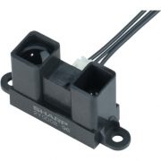
Overall, Sharp has several distance measures in the offer, where it individually should be looked which one is suitable for the task. This tutorial is designed for the Sharp GP2Y0A02YK0F, which is suitable for ranges from 20cm to 150cm. Distances outside this range are not measured correctly.
The following modules are available:
- GP2Y0A02YK0F (20cm – 150cm)
- GP2Y0A41SK0F (4cm – 30cm)
- GP2Y0A21 (10cm – 80cm)
- GP2Y0A710K0F (100cm – 550cm)
If you use a sensor other than the GP2Y0A02YK0F, you may need to adjust the steps. The data sheets are available on the Sharp homepage.
You will also need the following:
Operating the Infrared Distance Sensor
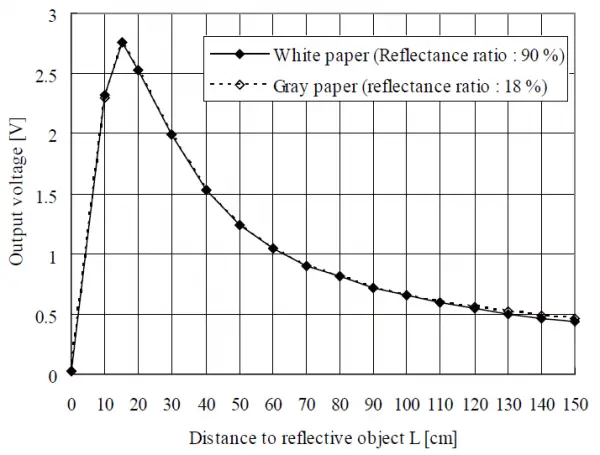
This IR sensor needs an input voltage between 4.5V and 5.5V, so it can be perfectly operated with the 5V of the Raspberry Pi. According to the datasheet, a different voltage is applied to the data pin, depending on how far the object measured by the sensor is. This is visible in the following graph:
Connection of the MCP3008
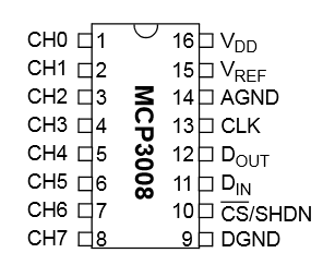
Since the outgoing voltage is analog, first we have to “translate” it with an analog-to-digital converter, so that we can evaluate it with the Raspberry Pi. This works best with an MCP3008 ADC.
This device is controlled via the Pi’s SPI bus and has eight channels to which analog voltages can be translated. These are divided into 2 ^ 20 so 1024 areas (0-1023). If the MCP3008 is connected to 3.3V, a signal of 1 means 0.00322V (3.22mV). Since the SPI bus of the Raspberry Pi works on 3.3V, no more power should be applied, otherwise, the GPIOs can be damaged.
The whole circuit looks like this:

| RaspberryPi | MCP3008 |
|---|---|
| Pin 1 (3.3V) | Pin 16 (VDD) |
| Pin 1 (3.3V) | Pin 15 (VREF) |
| Pin 6 (GND) | Pin 14 (AGND) |
| Pin 23 (SCLK) | Pin 13 (CLK) |
| Pin 21 (MISO) | Pin 12 (DOUT) |
| Pin 19 (MOSI) | Pin 11 (DIN) |
| Pin 24 (CE0) | Pin 10 (CS/SHDN) |
| Pin 6 (GND) | Pin 9 (DGND) |
The distance sensor has only three connections: red (5V), black (GND) and yellow, which is the data pin and connected to the MCP3008 ADC. For some, the alarm bells may sound and ask why a 5V module is connected directly, although the Pi’s SPI bus should not receive more than 3.3V input. The data sheet indicates that the output voltage of the sensor never exceeds 3V (see graph from the data sheet). Anyone who is afraid that something could happen to the Pi can put a voltage divider with 2 resistors in front of it, but this reduces the accuracy and also my used formula would have to be recalculated. In my tests, it never reached voltages above 2.7V (GP2Y0A02YK0F). This may differ for the other Sharp sensors.
Software for Reading the Distance
To control the MCP3008, the SPI bus must be activated. This works as follows:
sudo raspi-config
„8 Advanced Options“ -> „A6 SPI“ -> „Yes“.
After that, you have to confirm the restart.
In some cases, the module (spi-bcm2708) must also be entered in the / etc / modules file. For that just call
sudo nano /etc/modules
and add the following line at the end (if it does not exist):
|
1 |
spi-bcm2807 |
Now the spidev library can be installed, if it has not already been done:
sudo apt-get install git python-dev
git clone git://github.com/doceme/py-spidev
cd py-spidev/
sudo python setup.py install
Now that we have all the needed packages installed, we can create the script to measure the distance.
sudo nano ir_distance.py
The script has the following content:
|
1 2 3 4 5 6 7 8 9 10 11 12 13 14 15 16 17 18 |
#!/usr/bin/python import spidev spi = spidev.SpiDev() spi.open(0,0) spi.max_speed_hz=1000000 def readChannel(channel): val = spi.xfer2([1,(8+channel)<<4,0]) data = ((val[1]&3) << 8) + val[2] return data if __name__ == "__main__": v=(readChannel(0)/1023.0)*3.3 dist = 16.2537 * v**4 - 129.893 * v**3 + 382.268 * v**2 - 512.611 * v + 301.439 print "Distanz: %.2f cm" % dist |
We can do it now with (sudo python ir_distance.py), after we aim at an object, the distance is output.
What exactly happens here? First, the analog value (between 0 and 1023) is read out (line 15). However, since we want to know the voltage, the value is divided by 1023 and multiplied by 3.3 (volts).
Attention: In this case, we know (according to the data sheet) that the output voltage never exceeds 2.8V, although we supply the sensor with 5V. Other modules (analog and digital) often return signals with voltages as high as the applied voltage. Failure to do so may result in damage to the Raspberry Pi.
In line 16 of the script, I calculate the tension in centimetres. I have found the formula here and adapted it a little. For this, I have tested different distances and changed the factors a bit so that the calculated distance is as accurate as possible. As I mentioned at the beginning, this formula is only for the Sharp GP2Y0A02YK0F sensor. Since the other sensors provide analog signals in the similar range, this formula needs to be adjusted for the corresponding sensors (if anyone does that, I’d be happy if he posts it below).
Alternatively, one can also interpolate between the areas (data sheet) by storing all clues (volts, distance) and reading out the specific value and calculating the distance to the measured voltage using linear interpolation.
Sooner or later I will have to attach such a module to the inside of the rear window of my car and have a distance meter when parking in reverse – if someone does not yet know what he can do with it 😉
21 Comments
Hi
I’ve attempted this project. I am new to spi and spidev. ive added print(v) to display the registered input voltage as well as the calculated distance. I am getting very small voltage values and large distances ~280-340 cm. Otherwise my script and hardware is wired as in your description. Maybe my sensor is bad?
Any suggestions?
I am trying to get this ir working and it only reads as 301 cm – not sure what is wrong?
I am also having this issue. We have 4 people working on this and haven’t had any luck in the last several weeks.
I am also facing the same problem, it shows 301.44 cm as the distance.
For those seeing the 301.44cm reading:
The above circuit is using hardware SPI to wire the MCP3008. I found some of these chips don’t support hardware SPI but can still use the software SPI protocol.
Here’s how to wire the chip:
Lower row:
CH0: Data from sensor
Upper row (left to right, left is the “notch” position):
VDD -> 3.3V
VREF -> 3.3V
AGND -> GND
CLK -> GPIO 18
DOUT -> GPIO 23
DIN -> GPIO 24
CS/SHDN -> GPIO 25
DGND -> GND
Afterwards do NOT install the py-spidev package but instead get the following packages using PIP:
Adafruit_GPIO
Adafruit_MCP3008
Finally use the following modified python3 code:
import time
import Adafruit_GPIO.SPI as SPI
import Adafruit_MCP3008
CLK = 18
MISO = 23
MOSI = 24
CS = 25
mcp = Adafruit_MCP3008.MCP3008(clk=CLK, cs=CS, miso=MISO, mosi=MOSI)
while True:
v = (mcp.read_adc(0) / 1023.0) * 3.3
dist = 16.2537 * v**4 – 129.893 * v**3 + 382.268 * v**2 – 512.611 * v + 301.439
print(“Distance {:.2f}”.format(dist))
time.sleep(0.5)
Hope that helps!
@wintergarten
Hey there, when I try to lauch your script it just tells me this :
« File “Capteur_distance.py”, line 13
v = (mcp.read_adc(0) / 1023.0) * 3.3
^
IndentationError: expected an indented block »
What’s the issue? Very new to this so I have no idea. (btw I renamed the script to « Capteur_distance.py »)
Nevermind, I found out that there were a couple of errors in the code, but I got to correct them. The issue I have now is that my sensor gives me random values. Please note that I am using the GP2Y0A710K0F (100cm – 550cm) and not the GP2Y0A02YK0F (20cm – 150cm), the problem being that there aren’t any tutorials on the former…
@AlexP
I have the same issue like you,can you teach me how to solve it?
thanks in advance
This worked perfectly!! I made a single change though. When I installed Adafruit_MCP3008, I had to use pip3 rather than pip. Was receiving a no module found error prior to this. Thank you!
thanks so much for this. It worked for me
Thanks wintergarten, this worked much better but the figures i get are about double the expected distance. I am staying beyond the 20cm range. Anyone else see anything like this? using the following:
v = (mcp.read_adc(0) / 1023.0) * 3.3
dist = 16.2537 * v ** 4 – 129.893 * v ** 3 + 382.268 * v ** 2 – 512.611 * v + 301.439
Hi,
I have wired my mcp3008 like you say, but i have a lot of issue when i run your piece of code.
ImportError: No module named Adafruit_GPIO.SPI
-bash: ImportError:: command not found
thanks
Hi, can anyone help me when there is nothing in the script after doing all the steps and entering
sudo nano ir_distance.py
It doesn’t show the script…
The sensor I am using is GP2Y0A21.
I tested it according to the author’s method, but my value is 11.43cm. No matter how I move the sensor, the result is still the same.
What should I do?
I face similar problem. I get the value of 11.22 cm for every measure
I put this code in a loop for 30 seconds and I get one of two values at veery moment of time – 11.22/11.43 cm.
I did everything according to this guide.. I will try to find a solution
@wintergarten Thank you it helps me, I was trying with raspberry pi 3b+ and a Sharp 2Y0A21
for Sharp 0A41SK (input 3.3V) between 0.48 and 2.25 Volt ( 5-30cm)
dist = 8.53* v**4 -54.90*v**3 +131.26*v**2 -144.85*v +72.28
or simpler
dist = 13.91/v -1.48
Thanx for great article!
Excuse me, do you know if it is possible to change the MCP3008 for an ADS1115 and if it is possible, would there be a problem in obtaining data?
I have built this project and it works well initially, but after about 30 minutes there is an increasingly loud whistling noise coming from the Rasperberry Pi itself (not from the GP2Y0A02YK0F or the MCP3008) and the sensor starts to lose accuracy. I have tried it on a Pi2b and a PiZero and both exhibit the same behaviour.
Measuring the current draw on the 5v pin to the GP2Y0A02YK0F I’m seeing around 27ma at 4.8v.
On the pin to the MCP3008 I am measuring 3.3v and current draw below 200µA (as low as my meter goes).
Any ideas what could be causing this ?
I’ll answer my own post here. It seems that the quality of power supply is key !
Changed to another PSU and now measuring 5.1v to the GP2Y0A02YK0F and still getting accurate readings after an hour.
There is still a little high pitched noise from the Pi though, so I think I’ll have to buy a brand new PSU for it.