")
For many (outdoor) projects a distance measurement is necessary or advantageous. These small modules are available starting at 1-2 bucks and can measure the distance up to 4-5 meters by ultrasound and are suprisingly accurate. This tutorial shows the connection and control.
Hardware
Wiring
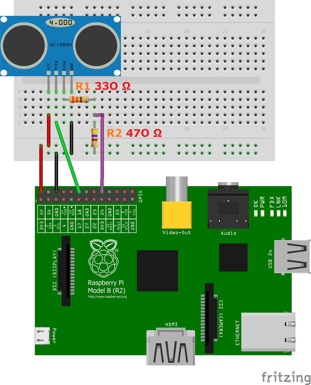
There are four pins on the ultrasound module that are connected to the Raspberry:
- VCC to Pin 2 (VCC)
- GND to Pin 6 (GND)
- TRIG to Pin 12 (GPIO18)
- connect the 330Ω resistor to ECHO. On its end you connect it to Pin 18 (GPIO24) and through a 470Ω resistor you connect it also to Pin6 (GND).
We do this because the GPIO pins only tolerate maximal 3.3V. The connection to GND is to have a obvious signal on GPIO24. If no pulse is sent, the signal is 0 (through the connection with GND), else it is 1. If there would be no connection to GND, the input would be undefined if no signal is sent (randomly 0 or 1), so ambiguous.
Here is the structure as a circuit diagram:
Script for controlling
To use the module, we create a new script
sudo nano ultrasonic_distance.py
with the following content:
|
1 2 3 4 5 6 7 8 9 10 11 12 13 14 15 16 17 18 19 20 21 22 23 24 25 26 27 28 29 30 31 32 33 34 35 36 37 38 39 40 41 42 43 44 45 46 47 48 49 50 51 52 53 |
#Libraries import RPi.GPIO as GPIO import time #GPIO Mode (BOARD / BCM) GPIO.setmode(GPIO.BCM) #set GPIO Pins GPIO_TRIGGER = 18 GPIO_ECHO = 24 #set GPIO direction (IN / OUT) GPIO.setup(GPIO_TRIGGER, GPIO.OUT) GPIO.setup(GPIO_ECHO, GPIO.IN) def distance(): # set Trigger to HIGH GPIO.output(GPIO_TRIGGER, True) # set Trigger after 0.01ms to LOW time.sleep(0.00001) GPIO.output(GPIO_TRIGGER, False) StartTime = time.time() StopTime = time.time() # save StartTime while GPIO.input(GPIO_ECHO) == 0: StartTime = time.time() # save time of arrival while GPIO.input(GPIO_ECHO) == 1: StopTime = time.time() # time difference between start and arrival TimeElapsed = StopTime - StartTime # multiply with the sonic speed (34300 cm/s) # and divide by 2, because there and back distance = (TimeElapsed * 34300) / 2 return distance if __name__ == '__main__': try: while True: dist = distance() print ("Measured Distance = %.1f cm" % dist) time.sleep(1) # Reset by pressing CTRL + C except KeyboardInterrupt: print("Measurement stopped by User") GPIO.cleanup() |
After that we run:
sudo python ultrasonic_distance.py
So every second, the distance will be measured until the script is cancelled by pressing CTRL + C.
That‘s it. You can use it many fields, but who still want to measure larger distances would have to rely on laser measuring devices, which, however, are much more expensive.
100 Comments
Thank you, I need this for a Magic Mirror. I want it to activate when someone is nearby, in front.
I have experimented with PIR, I always seem to find them a bit random but this should be good.
I found other examples of “how to do this”. This one, yours, worked immediately.
OK, so it is not my solution and I need to do much more to make my exact application work but “Thank You” so much for this proof of concept.
I am a little new. May I ask why you are resisting ground?
We want to create a pull resistor, such that the voltage status is never “random”.
Really the objective of those pair of resistors ( R1 & R2), is create a tension divisor in order to reduce the 5volt dc of the echo of the module SH-04 pin to less than 3.3 volt, because the GPIO (input dc or Out dc), operation voltage in all rtaspBerry Pi boards is 3.3 volts (Prof. JCGM) 🙂
Thank you for making it so easy to get playing with this sensor.
I only had 1k and 2.2k resistors available. Would that be the reason my measurements are off by about 1.7cm on the distances (0.5 – 2 meters) I tested?
My understanding is that a higher resistor will merely pull the voltage even lower than the target 3.3V needed to make the echo response safe for the pi’s GPIO pins.
Thanks again
Might be too late, but for future readers… it actually doesn’t make a difference. As long as the pi recognizes the signal as a high, it works. The only two possible outcomes are: 1. the pi doesn’t receive the high signal and your program either handles this, crashes, or runs forever because it’s waiting to receive a high or 2. the pi recognizes the signal as a high and therefore no error due to the pi/wiring/sensor. You could create a calibration curve for your sensor if you want the distances to be perfect. Also don’t forget that you’re doing the computation for the distance, so the speed of sound through air at the ambient temperature must be set properly for your ambient temperature.
Hey, I have problem where when I read the distance measurements on the sensor in loop, it reads 4-5 measurements and then it freezes on the terminal for a few seconds and then it starts reading in measurements again. I’m not sure what the problem do this issue is and how to fix this, I need the sensor to continuously measure the distance without pausing
I used this code and wired the circuit correctly with the 330 and 470 Ohm resistors but am getting values of over 100,000 cm even though my sensor is only 1 meter from a wall. Any ideas?
(also, the values are fluctuating quite a bit even with the sensor stationary; it’s not just off by some factor of 10…)
because your sensor is retarded
I am having the same problem also.
Me too
100 cm = 10 dm =1 m
You may have connected the wires in other positions than the positions must be
Hi.
I’ve made this and it worked perfect.
But i need to show it’s output in a webpage i configurated with lighttpd.
i know the page needs to be updated often. so i’ve done the following:
setTimeout(
function() {window.location.reload();},
500)
Here goes the whole page:
TCC – MEM
M.E.M
setTimeout(
function() {window.location.reload();},
500)
it depends of the materal of the wall, if it’s made of glass, the distance gonna be different, just like as wool.
ahh yess a wool wall
Hi, I need to connect 2 ultrasonic sensonrs and 1 gps, What pins should I use for the connection?
HI! was thinking of use this in my backhoe mount the sensor on the digging arm and messure down to digging level would it work ?? there is no digging system´s for home use… please leave a comment if this is possibel
Re: mount in backhoe … two significant challenges beyond mounting it somewhere it can make the measurement and, assuming that it’s not mounted on the cab, finding shielded cable with fine stranding and soft insulation that can withstand the bending at the arms joints, and a flexible plastic armor to encase it in.
The sensor measures the time delay of a sonic echo returning to infer distance. The echo from a hard flat surface is easy to interpret. The echo from a complex surface of stone(s), hard packed natural contour, loosened earth and material falling/fallen back into the hole will be a more complex and return from the sides of the hole will mimic a soft bottom to some extent, making it even more difficult to determine the hole depth. You may need multiple sensors to determine what’s happening at the sides of the hole to determine what’s happening at the bottom.
The sensor, whether mounted on the cab or the hydraulic arm will be mounted on a platform attached to a steel structure that transmits and mechanically amplifies vibration. The components aren’t made for that environment. Everything changes when it has to operate in a vibrating environment, even the choice of solder alloy. Subjecting the raspberry pi components to any significant vibration may shorten the operating life to minutes/hours/days. Make sure modules with clock circuits use a ceramic resonator not a quartz crystal. It will also add a large interfering signal to the echo return signal picked up. One of the key steps to making a successful sensor is going to be isolating the sensor platform from the vibration of the excavating machine. One way to avoid multiple evolutions of a vibration damping scheme is to begin with a multiple step approach something like conventional rubber vibration mounts to fix an 1/8 inch thick steel plate and then a layer of cork/tar adhesive to fix a lower mass aluminum plate to secure a sensor housing. Secure the cable in a flexible shape (a hairpin bend, an S bend, or a clock spring spiral in order of isolation and durability) to avoid transmitting vibration up the cable. It may or may not be necessary to do something more elaborate depending on the design details.
Once you get something mounted cover the sensor(s) with something like polyester cushion fill and get the signal is quiet enough to make figuring out the echo signal from the hole so you aren’t measuring vibration from the engine, hydraulic system, and boom arm as much as the hole.
If low cost ultrasonic distance sensors aren’t effective in this environment then an optical approach using something more like what a camera uses for infrared assisted autofocus may work.
Hello. I have a QUESTION. Do I first need to install Raspbian to create the python code in the raspberry Pi, or can I just create the Python file in my own computer and then move it to the Raspberry?
I think you do. New to raspberry pi platform, but i don’t think you can run python without an os on the processor. If it was C code i knew of ways, but it still would be a bit of trouble, with initialization (if there isn’t already an implementation of that). Easier to install the OS 😉
What I would like to see is a real time OS for raspberry <3 But maybe that's a bit out of the scope and purpose of the platform. When it gets to that level, just get the ARM board hahaha
You should be able to do it anywhere and transfer, but you have to remember to check if you need to do chmod for executables
Tried it and it worked at the first test. Almost creepy. But very cool!!
Thanks for this guide.
1)Why should to send trigger high and low , please explain working of ultrasonic sensor.
2)why StartTime = time.time()
StopTime = time.time()
Are initialised ,you can directly use in while statement isn’t it?
It frequently turns speaker on which causes ultrasound, the ultrasound bounce off the object its aiming on and it comes back to sensor, and the time between the response of time of that sound coming back is calculated and this measure the distance…
These look really cool!
I have use case where I would like to use multiple sensors in the same area.
Is there a way to set a unique frequency or amplitude (or any other attribute) of the ultrasonic signal so I can track which transmitter is heard by the receiver?
Thanks for any help!
I realize a simple solution would be to alter the timing of the transmissions, but I prefer to be able to just track each reception by source-of-signal rather than when the signal was received, if that’s possible.
The sensor has 2 piezo electric benders one for TX one for RX. The TX bender is driven with a step wavefront and the RX sensor gets a direct echo magnitude vs time. You could try to add something to absorb off-angle pulses to reduce interference if the sensors point in different directions but there’s no pre-made hardware that uses a more elaborate waveform that could be code division multiplexed or frequency division multiplexed to allow co-located sensors to operate simultaneously without interfering with each other. An optical method distance sensor, an IR distance sensor for example, might suit your need if sensors are intended to point in different directions.
it’s not printing anything when I run it, just staying silent indefinitely
turned out I looked at the wiring diagram of a different article on my phone then got to this page on my pc
i would like to call a script when an object is within range 0-100cm, please. I would like to ask how could i modify the aforementioned script please?
Do we need to use a 5V to 3.3V convertor for this? I was advised to use it when working with sensors as an overload can mess up the GPIO part of the Raspberry Pi.
this script will freeze and lockup in the while loop if it misses the pulse coming back; this isn’t a good way to read them
i am having truble with the par of the coad that says
if __name__ == ‘__ main__’
it is giving me an invalid syntax to that
Instead of “smart quotes”, the ‘curly’ quotes that word processors often auto-insert, since that’s what we use in literature/printing, you need the “dumb quotes”, or the straight quotes that you can find printed on the keyboard. A good programmer’s editor, such as Sublime Text, Atom, or Visual Studio Code (or even Windows’s own built-in Notepad), will help you overcome this. Search up “programmer’s editor programs” to find some to help out.
I’d also recommend looking into the lower-level editors, like nano, joe, ed, vim and emacs, but those aren’t for right now 😉
the code works for me until i come to interrupt it using Ctrl C. this is running in THONNY not a python shell using sudo..
Raspberry pi 4 any surgestions?
I made little changes, but it does not light up the LED when the distance is less than 50 cm. Please help
#Libraries
import RPi.GPIO as GPIO
import os
import time
GPIO.setwarnings(False) # Ignore warning for now
#GPIO Mode (BOARD / BCM)
GPIO.setmode(GPIO.BCM)
GPIO.setup(8, GPIO.OUT) # Set pin 8 to be an output pin and set initial value to low (off)
#set GPIO Pins
GPIO_TRIGGER = 18
GPIO_ECHO = 24
#set GPIO direction (IN / OUT)
GPIO.setup(GPIO_TRIGGER, GPIO.OUT)
GPIO.setup(GPIO_ECHO, GPIO.IN)
def distance():
# set Trigger to HIGH
GPIO.output(GPIO_TRIGGER, True)
# set Trigger after 0.01ms to LOW
time.sleep(0.00001)
GPIO.output(GPIO_TRIGGER, False)
StartTime = time.time()
StopTime = time.time()
# save StartTime
while GPIO.input(GPIO_ECHO) == 0:
StartTime = time.time()
# save time of arrival
while GPIO.input(GPIO_ECHO) == 1:
StopTime = time.time()
# time difference between start and arrival
TimeElapsed = StopTime – StartTime
# multiply with the sonic speed (34300 cm/s)
# and divide by 2, because there and back
distance = (TimeElapsed * 34300) / 2
return distance
if __name__ == ‘__main__’:
try:
while True:
dist = distance()
print (“Measured Distance = %.1f cm” % dist)
if dist< 50:
print ("LED ON")
GPIO.output(8,GPIO.HIGH)
time.sleep(1)
else:
print ("LED OFF")
GPIO.output(8,GPIO.LOW)
time.sleep(1)
# Reset by pressing CTRL + C
except KeyboardInterrupt:
print("Measurement stopped by User")
GPIO.cleanup()
Remove your time.sleep(1) to have the sensor read more often.
Pin 1 and 17 gives 3.3v dc power directly… Why can’t we use that instead of pin 2 and reduce the resistors…. Is it required to do the resistors part because when using multiple detectors it becomes difficult. Anyone respond for this
I found that I cannot get an accurate reading on the HC-SR04 using a raspberry pi. Arduino works fine with the equivalent code. I believe this is because of the non-pre-emptive multi-tasking OS on the pi – it’s not able to guarantee the required time-precision (10 microseconds). I verified this with the following simple code:
“`
import ctypes, datetime, time
libc = ctypes.CDLL(‘libc.so.6’)
def time_this():
t1=datetime.datetime.now()
libc.usleep(10)
t2=datetime.datetime.now()
print((t2-t1).total_seconds()*10**6)
while True:
time_this()
“`
The output varies quite wildly:
“`
Time elapsed: 3583.0 microseconds, expected 10 microseconds
Time elapsed: 1201.0 microseconds, expected 10 microseconds
Time elapsed: 3488.0 microseconds, expected 10 microseconds
Time elapsed: 1786.0 microseconds, expected 10 microseconds
“`
The accuracy gets better at larger time scales, e.g.
1 millisecond:
“`
Time elapsed: 2451.0 microseconds, expected 1000 microseconds
Time elapsed: 1455.0 microseconds, expected 1000 microseconds
Time elapsed: 1669.0 microseconds, expected 1000 microseconds
Time elapsed: 2668.0 microseconds, expected 1000 microseconds
“`
1 second:
“`
Time elapsed: 1001183.0 microseconds, expected 1000000 microseconds
Time elapsed: 1000388.0 microseconds, expected 1000000 microseconds
Time elapsed: 1000445.0 microseconds, expected 1000000 microseconds
Time elapsed: 1000253.0 microseconds, expected 1000000 microseconds
“`
So I’ve decided to use an arduino for this job, and use the pi for non-realtime applications.
I’m still curious to hear how others have managed to get any kind of usable accuracy on the HC-SR04 using a raspberry pi.
It seems like every sample I’ve seen online is polling for pin state, rather than setting up interrupt triggers on the echo pin — wouldn’t that get you a more reliable reading?
If I’m reading the data sheets correctly — the amount of time the echo pin is held high by the sensor is proportional to the distance the object is from the sensor.
So — setting up interrupts to time from the rising-edge to the falling-edge of the echo pin seems like it would be more accurate. Am I missing something here?
I am making a car and I need the PWM pins and I am using Raspberry Pi 3B+. Do you need to use Pin 18 or can you use any pin for the trigger
I have a question. I re-wrote the code above to use the GPIO.wait_for_edge() function. It seem to work, but only the first time. If I run the code the second time, it always fails. If I run it a third time, it works again. The funny part is, when I remove the GPIO.cleanup(), it always works! Anybody any idea what is going wrong? Below my code and the output from 2 runs in a row:
#! /usr/bin/python3
import RPi.GPIO as GPIO
import time
GPIO.setmode(GPIO.BCM)
GPIO.setwarnings(True)
TRIG = 23
ECHO = 24
GPIO.setup(TRIG,GPIO.OUT)
GPIO.setup(ECHO,GPIO.IN)
GPIO.output(TRIG, False)
print(‘Waiting a few seconds for the sensor to settle’)
time.sleep(2)
GPIO.output(TRIG, True)
time.sleep(0.00001)
GPIO.output(TRIG, False)
channel = GPIO.wait_for_edge(ECHO, GPIO.RISING, timeout=5000)
if channel is None:
print(‘Timeout occured, echo never started’)
else:
pulse_start = time.time()
channel = GPIO.wait_for_edge(ECHO, GPIO.FALLING, timeout=5000)
if channel is None:
print(‘Timeout occured, echo never stopped’)
else:
pulse_end = time.time()
pulse_duration = pulse_end – pulse_start
distance = pulse_duration * 17165
distance = round(distance, 1)
print (‘Distance first time: ‘, distance, ‘in cm’)
GPIO.cleanup()
Output from running the code:
>>> %Run Measure_Distance_Using_Ultra_Sound_HC-SR04_version2.py
Waiting a few seconds for the sensor to settle
Distance first time: 12.1 in cm
>>> %Run Measure_Distance_Using_Ultra_Sound_HC-SR04_version2.py
Waiting a few seconds for the sensor to settle
Timeout occured, echo never started
Timeout occured, echo never stopped
Traceback (most recent call last):
File “/home/pi/Measure_Distance_Using_Ultra_Sound_HC-SR04_version2.py”, line 35, in
pulse_duration = pulse_end – pulse_start
NameError: name ‘pulse_end’ is not defined
For some reason python3 didn’t like your use of single quotes but after replacing them with double quotes the code runs. It never works for me though. It only says the echo never started and never stopped.
Did you ever get this working? I’m trying it out because the code from the article doesn’t work for me either, it only gives me output of 0.5cm or 0.6cm no matter what.
There is a problem with your code in the second “else” statement. This is the only time pulse_end is defined. Therefore, it is never defined so long as the if statement is true.
Bonjour tout le peuple RASPBIAN.
J’suis nouveau dans le forum et je dois faire fonctionner plusieurs capteurs ultrason avec la RASPBERRY PI 3 B et je ne sais comment leur faire fonctionner.
Merci de bien vouloir me contacter en cas de solution.
Can you explain the formula used to decide what values of resistors are needed?
Is it
Vout = Vin × R2/R1+R2
If so, Vout is 3.3V and Vin is 5V right? Now I tried putting 330 ohm and 470 ohm and could not get right values. Am I using the wrong formula? Can you kindly guide?
I tried this out, but even after triple-checking the wirering it still would not work. The only thing I could find is that I used 10kΩ resistors insted of 330Ω & 470Ω. Would that affect it? Do I need to order those resistors?
I tried this out, but even after triple-checking the wirering it still would not work. The only thing I could find is that I used 10kΩ resistors insted of 330Ω & 470Ω. Would that affect it?
The resistors are used as a voltage divider to get the 5v down to something within spec (3.3v max) for the pi gpio pins. If both are the same then you will get half the voltage (2.5v), which is in spec, but just barely above the 1.8v the pi is looking for to trigger a high on the pin you have connected to echo. It should work, so you likely have another issue, but it could not hurt to get two different resistors with one no less than half the resistance of the other.
What about the required 5V on the trigger pin? In that proposal you’re only providing the pulse with a 3.3V, wich is not as per spec of the sensor module.
I was thinking of using a transistor that would triggered at 3.3V at the base.
Let me know what you think.
Will this work with a Pi Zero W?
hi, I tried to connect this sensor with raspberry, with 70m distance between rapsberry and sensor. Is it possible to read this sensor? Do I need amplifier?
Hello, I’m using 4 ultrasonic what changes should I make to the script? Thank you.
Thank you for the tutorial. I got it working on a Pi Zero W. Unfortunately, I just found that the minimum distance the ultrasonic sensor can detect is 2cm as per the datasheet. I’m trying to use it in conjunction with an MLX90614 sensor with a 90` FOV so yeah. The object has to be really close to the sensor (1 -2cm) to ensure full coverage to achieve maximum accuracy of the readings.
Hi does anyone have any solution for when my ultrasonic sensor returns negative value?
The difference for this setup , R1 i used 1K ohms and for R2 i used 2K ohms.
This example did not work for me on a Raspberry Pi 0 W. I tried my HC-SR04 with an Arduino and it worked. I found another tutorial for the Pi 0 W and tried that. It worked. Using the same circuit (and remapping the GPIOS to match, this example still did not work.
I did get this working on a Pi Zero W. Apparently cabling issues prevented it from working earlier.
For line 47;
print (“Measured Distance = %.1f cm” % dist),
It is giving an error saying it’s an invalid character with “Measured” highlighted specifically. Please help.
Pingback: https://hernswe.gonevis.com/scientists-model-true-prevalence-of-covid-19-throughout-pandemic/
Pingback: canadian pharmacy no prescription
i really love the site
me too my guy
Great