
The ESP8266 NodeMCU is a small microcontroller that has GPIOs and can connect to the Internet via WLAN. This and the low price make it very interesting compared to Arduinos, for example. In upcoming tutorials, we want to use the inexpensive ESP8266 modules to send data via a Wifi connection to the Raspberry Pi, which acts as the “core”.
This tutorial is about the introduction as well as the general setup and first start with an ESP8266 NodeMCU.
Required Hardware Parts
There are different models of the ESP8266, the cheapest (ESP-01) only has four GPIO pins. This should be sufficient for minimal applications. If more hardware pins are needed, the ESP-12 is the better choice. The latter is also available as a “development board”, which makes adapters unnecessary.
Before we start, you should make sure which version is suitable for you. This and all upcoming tutorials will be compatible with both versions.
- The NodeMCU ESP-12 module has the advantage that it can be connected via a MicroUSB cable and has a reset button. If you only need the module without a development board (e.g. due to space constraints), you can also purchase this separately.
If you don’t have an integrated board, you need the following:
If you want to recreate the example at the end, you should also have a few LEDs there.
Setup & Wiring
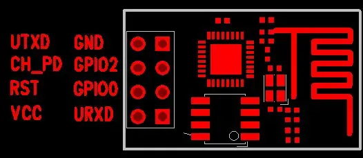
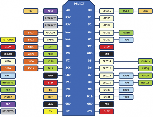
First of all, we have to connect the ESP8266 to a USB port on our computer. With the development board, it is sufficient to connect a micro USB cable. Without such a board we have to use the USB-TTL adapter. For this, it is important that we know the pin assignment of our ESP module.
For the two ESP-01 and ESP-12 I have inserted the pin assignment here:
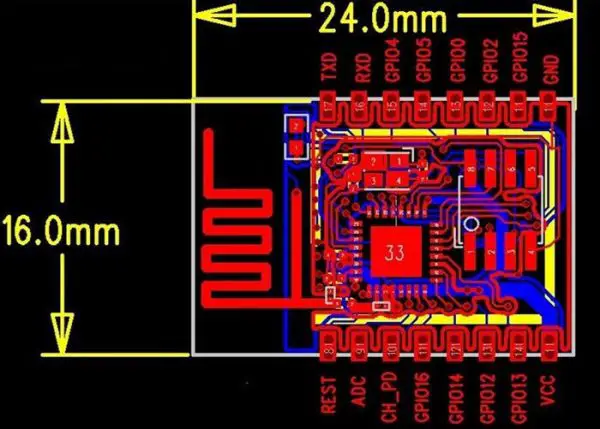
An assignment of all models (ESP-05, ESP-07, etc.) can be found here.
Now we have to connect the module to the FT232 USB adapter. This has 6 pins, of which we will use 4. The labelling of the pins is not directly visible since it is between the jumper and the actual pins.
The following pins of the ESP8266 NodeMCU module are first connected to the USB-TTL converter using jumper cables:
| ESP8266 | FT232 USB-TTL Serial Adapter |
|---|---|
| VCC | VCC |
| CH_PD | VCC |
| TXD | Tx |
| GND | GND |
| RXD | Rx |
| GPIO 0 | GND (temporary) |
By the way, the connection of GPIO0 to GND is only important when flashing. After the firmware has been successfully flashed, you can disconnect this pin from the GND.
Firmware Flashing
First, connect the USB adapter to your PC. The ESP8266 should be recognized automatically and the drivers should be installed automatically under Windows 7/8/10.
Then we need the NodeMCU Flasher Tool. There is a 32-bit and 64-bit version of this, which must be downloaded according to the operating system.
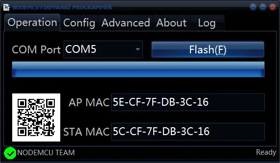
Start the program and select the corresponding port to which the ESP82166 is connected. Usually this is recognized automatically (as long as no more than one module is connected). After checking, press Flash (F) and wait for the process to complete. The Mac address should be displayed directly:
 The development team is probably in the process of making the tool available for Linux and Mac. If you want to update the firmware one day, you can find more information here.
For example, you can load custom firmware from here (with more libraries included as standard (such as http, etc.). This is in the “.bin” file format and can be used in the “Config” tab instead of the predefined firmware Connect that the baud rate on these custom builds is 115200 and not 9600 (if you use them).
Once the firmware has been successfully transferred, you can disconnect GPIO0 from GND and close the flashing tool.
Connecting to the ESP8266
The ESP8266 NodeMCU microcontroller can be programmed using the LUA language (by the way, this also occurs in our automatic telegram script). In order to transfer the program code to this, we first have to establish a serial connection. The easiest way to do this is with the help of a tool.
For this, I use the “ESPlorer” tool, which was written in Java and can, therefore, be used on all operating systems. First, download this from the developer page and unzip it.
Under Windows operating systems it is sufficient to start the associated “ESPlorer.bat”.
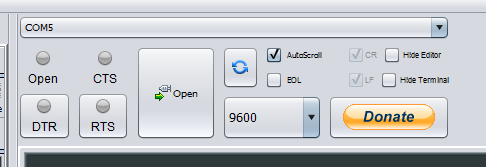
The selection of the port is available again in the right tab. Select the corresponding port (for me this is COM5) with baud rate 9600 (in earlier versions this was 115200). Now click on the Open button.
Usually not much happens at first, except for this text:
PORT OPEN 9600

Communication with MCU..
You have to restart the microcontroller first. Pressing the reset button on a development board is sufficient. Without a board, the RST pin (see above for assignment) must be connected briefly to GND. The following message then appears:
Got answer! Communication with MCU established.
AutoDetect firmware...

Can't autodetect firmware, because proper answer not received (may be unknown firmware).
Please, reset module or continue.

Self adjust flash size.

NodeMCU 0.9.5 build 20150318  powered by Lua 5.1.4
lua: cannot open init.lua
>
You have now made it! Here commands can already be entered via LUA, which are then executed once. For example, you can enter the following at the bottom:
print("Hello World")
Of course, it is also possible to have the program code executed immediately after starting. To do this, the code must be written to an “init.lua” file, but we will get to that in a moment.
By the way: In theory, it is also possible to connect via Putty or Arduino IDE or any program that can establish a serial connection. In my opinion, the ESPlorer Tool is the most convenient option.
First Test – Server
The NodeMCU page has some examples (below), two of which we want to try out.
The first example is a small web server that runs under the local IP address of the ESP8266. Of course, this first has to be connected to the WLAN.
In the left side of the ESPlorer you can copy the following code:
|
1 2 3 4 5 6 7 8 9 10 11 12 13 |
wifi.setmode(wifi.STATION) --wifi.sta.config("SSID","password") wifi.sta.config {ssid=SSID, pwd=SSID_PASSWORD} -- a simple http server srv=net.createServer(net.TCP) srv:listen(80,function(conn) conn:on("receive",function(conn,payload) print(payload) conn:send("<h1> Hello, NodeMcu.</h1>") end) end) |
Of course, the WLAN data (SSID = name, password) must be replaced with that of your network.
Then press “Send to ESP” (you may have to save the file locally beforehand).
To find out the IP address, you can enter the following in the right view below:
|
1 |
print(wifi.sta.getip()) |
This gives an output like this:
192.168.1.77 255.255.255.0 192.168.1.1
The first IP address specified is that within the local network. If your computer is also in this network, you can simply enter this IP in your browser and the following should appear:
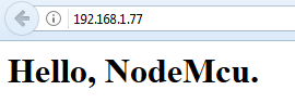
As soon as you call this up, the log in the right window of the ESPlorer should also display something.
If you want to put the file in the autostart, save it under “init.lua” and transfer it to the ESP.
If you want to delete it one day, you can do it as follows (documentation):
file.remove("init.lua")
Connecting the ESP8266 NodeMCU GPIO
Finally, we want to use the GPIOs and let an LED light up.
Make sure that the GPIO numbering, as with the Raspberry Pi, does not match the pin assignment. For example, with ESP-01 GPIO0 = Pin3 and GPIO2 = Pin4. In the code, we give the pin numbering. The assignment can be found here.
| IO index | ESP8266 pin | IO index | ESP8266 pin |
|---|---|---|---|
| 0 | GPIO16 | 7 | GPIO13 |
| 1 | GPIO5 | 8 | GPIO15 |
| 2 | GPIO4 | 9 | GPIO3 |
| 3 | GPIO0 | 10 | GPIO1 |
| 4 | GPIO2 | 11 | GPIO9 |
| 5 | GPIO14 | 12 | GPIO10 |
| 6 | GPIO12 |
With the ESP-12 NodeMCU it should be noted that the D-Pins (D0, D1, etc.) do not represent the GPIO numbers, but the IO / Pin numbering:
With the following script you can flash an LED on GPIO2 (long end of the LED on the GPIO, short end on GND):
|
1 2 3 4 5 6 7 8 9 |
pin = 4 -- GPIO2 gpio.mode(pin,gpio.OUTPUT) while true do gpio.write(pin,gpio.HIGH) tmr.delay(1000000) gpio.write(pin,gpio.LOW) tmr.delay(1000000) end |
On the reference page of NodeMCU you can find further small examples.
Which projects (especially in relation to the Raspberry Pi) should I implement next?