
The ESP8266/NodeMCU is a small and inexpensive microcontroller with an integrated wireless LAN module, which is particularly popular in the field of home automation. In addition to programming using the “Lua” language, the ESP8266 can also be programmed with the classic Arduino IDE (with C ++ and other modules).
Since many published libraries for the NodeMCU were written in C ++, we need the IDE that was originally provided for the Arduino. This IDE also supports the ESP8266 thanks to an extension. This tutorial is about the exact installation and a first test. In addition, we test the ESP by writing a small program that lights up an LED and connects to a wireless LAN network.
One of the advantages of the ESP32 compared to a (mini) Arduino is the integrated wifi chip. While the Arduino can only have a lot added via a shield, the ESP8266 offers this by default and has a lower price. So overall there are some good reasons for an ESP8266.
Required Hardware Parts
The ESP8266 is available in different versions. All models have a built-in W-LAN adapter and the cheaper the model, the fewer programmable GPIO pins the microcontroller has. You can find an overview in this article.
So that we can easily program the NodeMCU via USB, we use an ESP32. The additional LEDs are only there if you want to run the IO pin test at the end of the tutorial.
- ESP8266: model ESP32
- Micro USB cable
- Breadboard
- optional: LED kit
- optional: jumper cables
Preparing the ESP8266 Arduino IDE
The basis is the official Arduino IDE, which you can download here. There are versions for Windows (from XP), Mac OS and various Linux distributions (also for ARM architecture).
So download and install the IDE. After that, it may start automatically – if not, we start it manually. This creates initial configurations and folders. Under Windows 10 this is among others “C: Users [username] Documents Arduino”. You can find this directory by opening the Arduino IDE and selecting “File” -> “Preferences” (Sketchbook location).
Then we still need a Git client. This is already pre-installed on most Linux systems. Git-SCM can be used for Windows (but also for Mac and Linux). Download and install this tool as well. Then you will see the following UI:
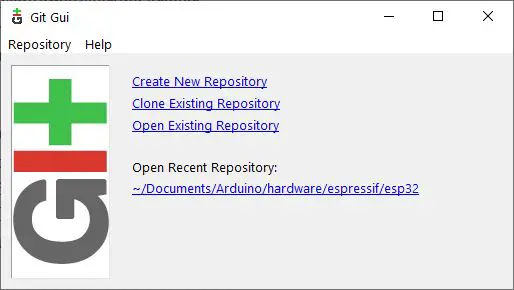
Select “Clone Existing Repository”. The following must be entered in the following dialogue:
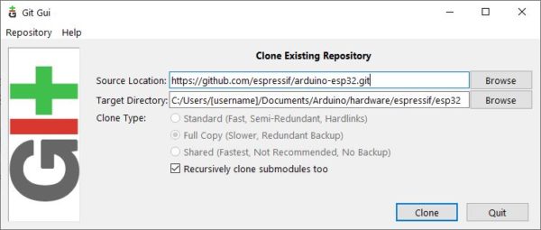
Here again to copy (replace [username] with your Windows user name. On other systems you have to adapt the path accordingly. Then press “Clone”).
https://github.com/espressif/arduino-esp32.git
C:/Users/[username]/Documents/Arduino/hardware/espressif/esp32
In the latter directory, there is a subfolder “tools”. Inside there is a file called “get.exe”. We do this with a double click:
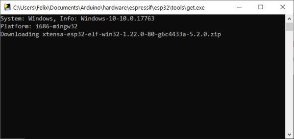
The window closes automatically after the download is complete.
Now it is time to connect the ESP32 to the PC via USB. Wait a moment until all necessary drivers have been installed and then start the Arduino IDE.
Further Installation Steps
Open the IDE and go to “File” -> “Preferences”. There you paste the following URL (Additional board administrator URLs):
http://arduino.esp8266.com/stable/package_esp8266com_index.json
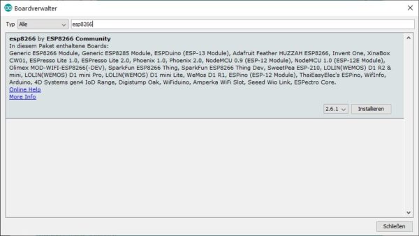
Then you can search for “ESP8266” under “Tools” -> “Boards” -> “Boardmanager” (at the top) and install the package.
Under “Tools” -> “Board” select the “Generic ESP8266 Module”. If you have not connected any other devices, the COM port should have been automatically recognized correctly.
Now you can already upload a simple (empty) sketch.
Connection and First Test of the NodeMCU Using the Arduino IDE
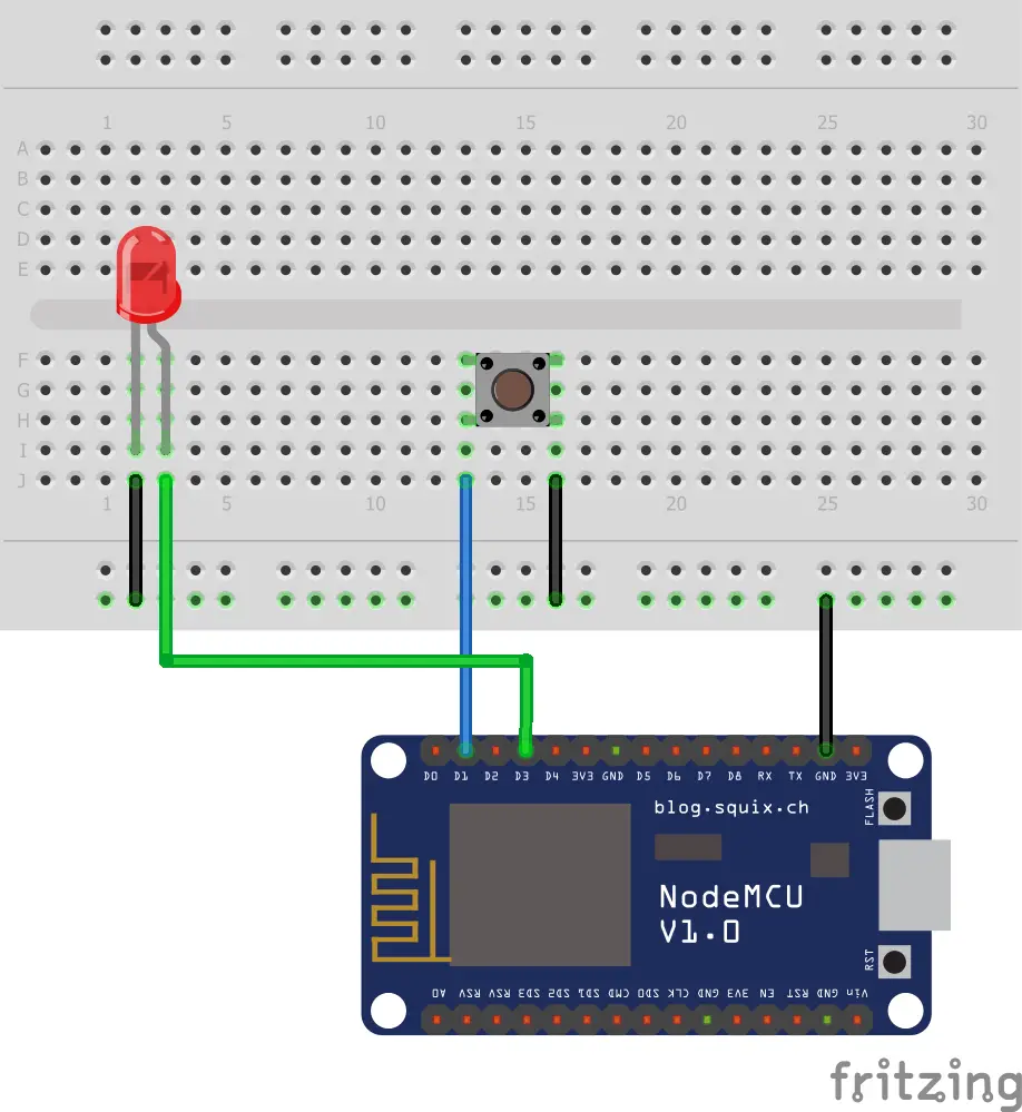
Now that we have set up the ESP8266 Arduino IDE, we will write the first little C ++ code with which we will light up an LED. Now connect the ESP microcontroller to the breadboard and take a small LED with the color of your choice. This has two ends: the positive voltage (+) comes to the longer end and the shorter end is connected to ground (GND).
For larger circuits, you usually use transistors or relays, but in this case, the current from one IO pin is enough to make the LED light up. If you want, you can also add a button so that the LED only lights up when the button is pressed. But we won’t go into that in more detail for now (that could be a small additional task 😉 )
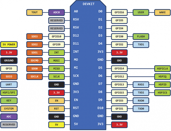
 It is important to note that the D3 pin is not the pin that we specify, but corresponds to this GPIO-0. Here you will also find all GPIO pins of an ESP32 Dev module:
Insert the following code into the Arduino IDE and press the “Upload” button.
|
1 2 3 4 5 6 7 8 9 10 11 12 13 14 15 16 17 18 19 20 21 22 23 24 25 26 27 28 29 30 31 32 33 34 35 |
#include <ESP8266WiFi.h> #define LED_BUILTIN 0 void setup() { pinMode(LED_BUILTIN, OUTPUT); // Initialize the LED_BUILTIN pin as an output Serial.begin(115200); Serial.println(); WiFi.begin("NETWORK_SSID", "WIFI_PASSWORD"); // replace Serial.print("Connecting"); while (WiFi.status() != WL_CONNECTED) { delay(500); Serial.print("."); } Serial.println(); Serial.print("Connected, IP address: "); Serial.println(WiFi.localIP()); } // the loop function runs over and over again forever void loop() { digitalWrite(LED_BUILTIN, LOW); // Turn the LED on (Note that LOW is the voltage level // but actually the LED is on; this is because // it is active low on the ESP-01) delay(1000); // Wait for a second digitalWrite(LED_BUILTIN, HIGH); // Turn the LED off by making the voltage HIGH delay(2000); // Wait for two seconds (to demonstrate the active low LED) } |
The ESP8266 will restart automatically and the LED will start flashing.
You can find the complete log (serial output) “Tools” -> “Serial Monitor” or by pressing CTRL + Shift + M.
By the way: You can find many other smaller ESP8266 examples for the Arduino IDE in this Github repository.